
Vehicle power transmission device

A technology for power transmission devices and vehicles, applied in the direction of transmission devices, belts/chains/gears, mechanical equipment, etc., can solve problems such as vibration and unbalanced load offset, and achieve the effect of reducing vibration

Active Publication Date: 2017-12-01
HONDA MOTOR CO LTD
View PDF6 Cites 0 Cited by
  • Summary
  • Abstract
  • Description
  • Claims
  • Application Information

AI Technical Summary

Problems solved by technology

[0002] In a power transmission device for a vehicle including a plurality of transmission units arranged side by side in the axial direction, there is a problem that periodic eccentric loads are applied because the eccentric disc rotates eccentrically around the input shaft with mutually different phases. The bearings that support both ends of the input shaft cause vibration
[0007] However, when the power transmission device for a vehicle is equipped with eight transmission units with a phase difference of 45° at equal intervals in the axial direction, according to the technical idea of ​​the invention described in Patent Documents 1 and 2, it is impossible to make the bearing acting on the input shaft Offset loads on the

Method used


Image

  • Vehicle power transmission device
  • Vehicle power transmission device
  • Vehicle power transmission device

Examples


Embodiment Construction

[0062] Below, based on Figure 1 to Figure 21 Embodiments of the present invention will be described.

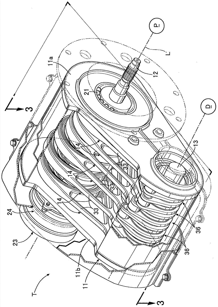
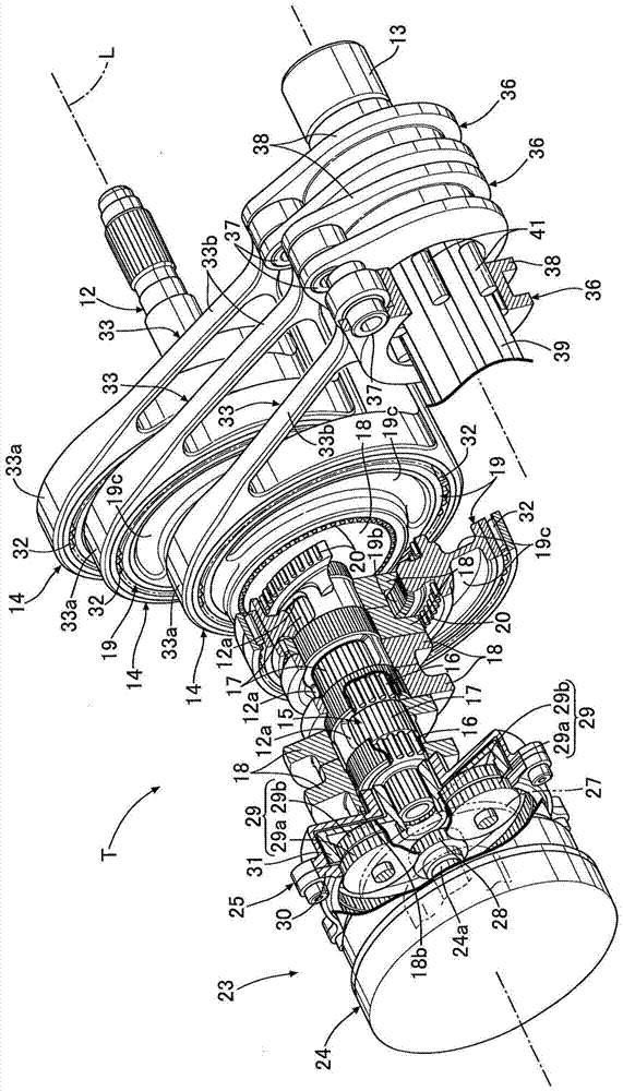
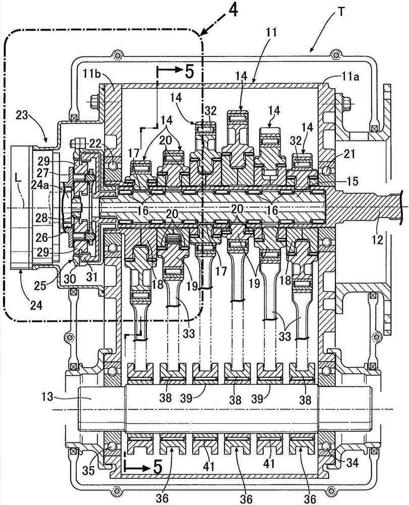
[0063] like Figure 1 to Figure 5 As shown, the input shaft 12 and the output shaft 13 are supported on a pair of side walls 11a, 11b of the transmission case 11 of the continuously variable transmission T for motor vehicles in parallel with each other, and the rotation of the input shaft 12 connected to the engine P passes through 6 A transmission unit 14, the output shaft 13 and the differential D are transmitted to the drive wheels. A transmission shaft 15 sharing an axis L with the input shaft 12 is relatively rotatably fitted inside the hollow input shaft 12 via seven needle bearings 16 .

[0064] Furthermore, the power transmission device for a vehicle according to the present invention actually includes eight transmission units 14 , but here, for convenience, the number of transmission units 14 will be described as six. The structures of the six transfer units 14 a...


PUM


Abstract

The present invention provides a power transmission device for a vehicle that reduces or completely abrogates a partial load on a bearing of an input shaft of a power transmission device for a vehicle having eight transmission units. In the eight transmission units of the power transmission device, the axial distance between the first unit (A) and the first inverse unit (A') and the axial distance between the fourth unit (D) and the fourth inverse unit (D') are both p; the axial distance between the second unit (B) and the second inverse unit (B ') and the distance between the third unit (C) and the third inverse unit (C') are both q; the distance p and the distance q satisfy the relationship of 1 < q / p < [2sin(67.5 DEG) - sin(22.5 DEG)] / sin(22.5 DEG), and therefore, the partial loads on the first and second bearings (22, 21) cancel each other by each transmission unit (14) , so that the vibration can be reduced.

Description

technical field [0001] The present invention relates to a vehicle power transmission device that transmits rotation of an input shaft connected to a drive source to an output shaft connected to drive wheels, including eight transmission units arranged side by side in the axial direction. Background technique [0002] In a power transmission device for a vehicle including a plurality of transmission units arranged side by side in the axial direction, there is a problem that periodic eccentric loads are applied because the eccentric disc rotates eccentrically around the input shaft with mutually different phases. The bearings that support both ends of the input shaft cause vibration. [0003] The total eccentric load acting from a plurality of transmission units on the bearings supporting the both ends of the input shaft changes according to the distance between the bearing and each transmission unit and the phase of the eccentric disk of each transmission unit, so , if the p...

Claims


Application Information

Patent Timeline
Patent Type & Authority Patents(China)
IPC IPC(8): F16H37/12
CPCF16H37/12
Inventor 西村优史
Owner HONDA MOTOR CO LTD
Learn More