
High-speed hosiery machine

A sock machine, high-speed technology, used in textiles and papermaking, weft knitting, knitting and other directions, can solve the problems of unfavorable high-speed sock machine, long yarn path, inability to keep up with high-speed production rhythm, etc. The effect of improved sensitivity, reduced misoperation, and simple structure

Inactive Publication Date: 2016-08-03
HAINING WANLU KNITWEAR
View PDF6 Cites 0 Cited by
  • Summary
  • Abstract
  • Description
  • Claims
  • Application Information

AI Technical Summary

Problems solved by technology

[0003] In order to adapt to the broken thread detection of the photoelectric detection switch, the current yarn feeding mechanism has a long path for the yarn to pass, which is not conducive to the high speed of the hosiery machine. At the same time, due to the high speed, the needle broken detection device of the knitting mechanism needs to be higher Sensitivity, otherwise it will not be able to keep up with the high-speed production rhythm

Method used

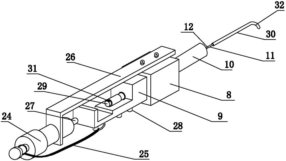

Image

  • High-speed hosiery machine
  • High-speed hosiery machine
  • High-speed hosiery machine

Examples


Embodiment Construction

[0026] The present invention is described in further detail below:

[0027] The present invention is a high-speed hosiery machine, which includes a yarn feeding mechanism for supplying yarn to the knitting mechanism and a control mechanism for controlling the knitting mechanism. A plurality of pallets 3 distributed sequentially from bottom to top, each pallet 3 is provided with a bobbin seat 2, except for the bobbin seat 2 on the uppermost layer, the bobbin seats 2 on the pallets 3 of other layers, other Each supporting plate 3 above is provided with the lead hole 4 that is used to guide this bobbin seat 2, and a plurality of mechanical switches 5 are arranged on the uppermost supporting plate 3, and this mechanical switch 5 is provided with fork 6, and the fork 6 One end is the hanging thread end 7, and the other end of the swing bar 6 is connected to the mechanical switch 5 in rotation, and the swing link 6 is connected with a reset mechanism, which is used to drive the swin...


PUM


Abstract

The invention provides a high-speed hosiery machine. A path through which yarns pass is shortened by a yarn feeding mechanism; meanwhile, a broken needle detection device has relatively high sensitivity; furthermore, the high-speed hosiery machine is relatively simple and compact in structure and comprises the yarn feeding mechanism for supplying yarns to a weaving mechanism, and a control mechanism for controlling the weaving mechanism, wherein the yarn feeding mechanism comprises mechanical switches (5); the weaving mechanism is provided with the broken needle detection device; one end of each mechanical switch and a conductive tube of the broken needle detection device are connected in parallel to form a first parallel end which is electrically connected with one end of a power supply; the other end of each mechanical switch and a conductive rod of the broken needle detection device are connected in parallel to form a second parallel end which is electrically connected with an input end of a high voltage to low voltage signal conversion circuit; an output end of the signal conversion circuit is electrically connected with the other end of the power supply; and a signal output end of the signal conversion circuit and a driving device are respectively electrically connected with a control mechanism.

Description

technical field [0001] The invention relates to the technical field of socks manufacturing equipment, in particular to a high-speed socks machine. Background technique [0002] The sock knitting machine is one of the important equipment for producing socks. The sock knitting machine is composed of a yarn feeding mechanism, a knitting mechanism and a control mechanism. The yarn feeding mechanism supplies yarn to the knitting mechanism, and the knitting mechanism is controlled by the control mechanism. Automated production reduces labor costs and improves work efficiency. [0003] In order to adapt to the broken thread detection of the photoelectric detection switch, the current yarn feeding mechanism has a long path for the yarn to pass, which is not conducive to the high speed of the hosiery machine. At the same time, due to the high speed, the broken needle detection device of the knitting mechanism needs to be higher Sensitivity, otherwise it will not be able to keep up w...

Claims


Application Information

Patent Timeline
Patent Type & Authority Applications(China)
IPC IPC(8): D04B15/42D04B35/14D04B35/18
CPCD04B15/42D04B35/14D04B35/18
Inventor 吴伟东
Owner HAINING WANLU KNITWEAR
Learn More