Cold head for cryogenic refrigerating machine

A refrigeration refrigeration and cold head technology, applied in refrigerators, gas cycle refrigerators, refrigeration and liquefaction, etc., can solve problems such as performance loss, and achieve the effect of reducing costs and reducing the risk of oil penetration

Active Publication Date: 2016-07-27
レイボルドゲーエムベーハー
View PDF5 Cites 0 Cited by
  • Summary
  • Abstract
  • Description
  • Claims
  • Application Information

AI Technical Summary

Problems solved by technology

Another disadvantage is that loss of performance occurs due to the existing hysteresis of the relief valve between opening and closing pressure

Method used


Image

  • Cold head for cryogenic refrigerating machine
  • Cold head for cryogenic refrigerating machine
  • Cold head for cryogenic refrigerating machine

Examples


Embodiment Construction

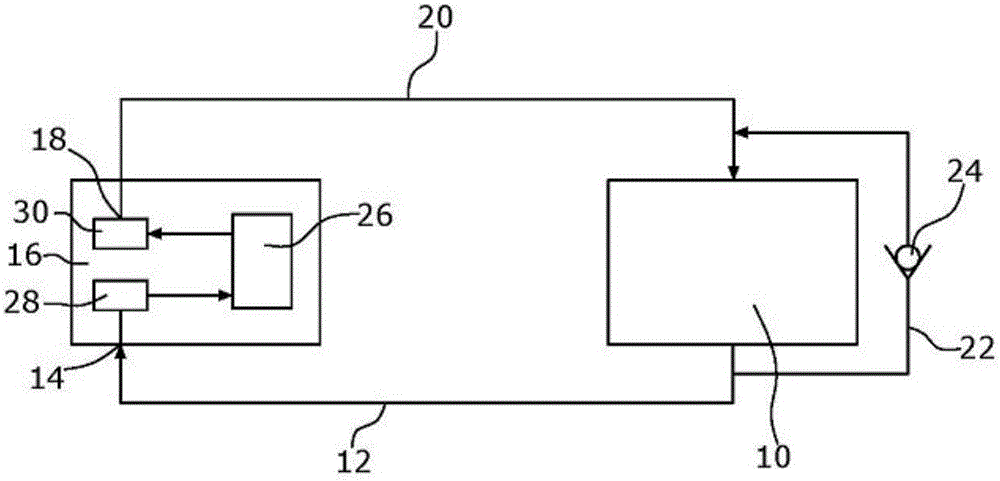
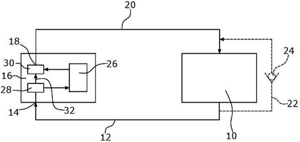
[0016] The refrigerated refrigerator of the prior art ( figure 1 ) includes a compressor 10 that compresses a refrigerant such as helium. On the high pressure side, the compressor 10 is connected via a conduit 12 to a high pressure connection 14 of a cold head 16 . The low pressure connection 18 of the cold head 16 is connected to the low pressure side of the compressor 10 via a conduit 20 . In order to avoid overloading on the compressor 10 , a check valve 24 is arranged in the return line 22 which connects the high-pressure side of the compressor 10 to the low-pressure side of the compressor 10 .

[0017] Within the cold head 16 a working chamber 26 is provided in which the figure 1 Displacer piston not shown. An inlet valve 28 is connected to the high pressure connection 14 such that compressed refrigerant flows into the working chamber 26 when the inlet valve 28 is open. The expanded refrigerant may be directed to the low pressure connection 18 via a discharge valve 30...


PUM


Abstract

A cold head for cryogenic machines comprises a displacer (72, 76) mounted in a working chamber (38, 40, 46) of a housing (34, 36). The cold head also has a high-pressure connection (64) for supplying highly compressed refrigerant and a low-pressure connection (60) for discharging expanded refrigerant. Also provided is a control valve arrangement (58) for controlling the supply and discharge of refrigerant. According to the invention there is a bypass channel (80) connecting the high-pressure connection to the low-pressure connection.

Description

technical field [0001] The present invention relates to cold heads for refrigeration refrigerators. Background technique [0002] WO 94 / 29653 describes a cold head for a refrigeration refrigerator operating with helium as working gas and connected to high and low pressure sources. The cold head comprises a multi-channel control valve which controls the respective connection of the high pressure inlet and the low pressure inlet to the piston cylinder unit and the working chamber of the cold finger on the warm side. At one of its ends, the displacer, which may include a regenerator, defines a warm-side working chamber, and at the opposite end, it defines a cold-side working chamber. Although the regenerator is periodically reciprocated by the piston-cylinder unit, heat is continuously obtained from the coldhead's housing. Using a cold head with a single stage displacer, temperatures down to about 30K can be generated. Using a two- or three-stage displacer, temperatures belo...

Claims


Application Information

Patent Timeline
Patent Type & Authority Applications(China)
IPC IPC(8): F25B9/14
CPCF25B2309/006F25B9/14
Inventor 格哈德·威廉·沃尔特霍尔格·迪茨
Owner レイボルドゲーエムベーハー
Why Eureka
Try Eureka