Method for generating an HDR image of a scene based on a tradeoff between brightness distribution and motion

一种亮度分布、场景成像的技术,应用在图像增强、图像分析、图像通信等方向,能够解决HDR频率低、运动伪像、不能避免运动模糊等问题,达到降低帧率、扩展范围的效果

Active Publication Date: 2016-07-27
INTERDIGITAL CE PATENT HLDG
View PDF7 Cites 3 Cited by
  • Summary
  • Abstract
  • Description
  • Claims
  • Application Information

AI Technical Summary

Problems solved by technology

However, because some objects in the scene may move (or the camera may move) during the successive exposures that capture each HDR image used to construct the video, and because these different exposures capture the scene at different times, the merging of these exposures may produce motion artifacts
Also, since the frequency of the HDR image is a division of the frame frequency allowed by the video image capture device, the HDR frequency may be too low to avoid motion blur

Method used


Image

  • Method for generating an HDR image of a scene based on a tradeoff between brightness distribution and motion
  • Method for generating an HDR image of a scene based on a tradeoff between brightness distribution and motion
  • Method for generating an HDR image of a scene based on a tradeoff between brightness distribution and motion

Examples


Embodiment Construction

[0036]Those skilled in the art will appreciate that any flowcharts, diagrams, etc. presented herein represent conceptual views of illustrative circuits embodying the invention. It may be substantially represented in a computer readable medium and thus executed by a computer or processor, whether or not such computer or processor is explicitly shown.

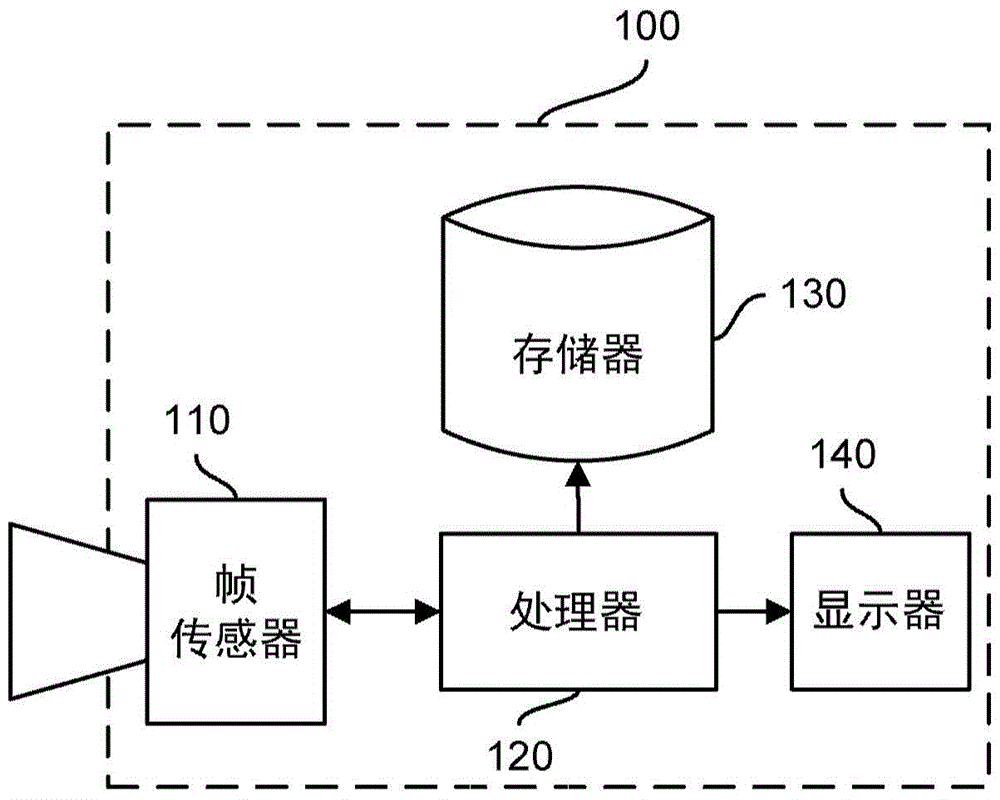
[0037] According to the main embodiment of the present invention, figure 1 A simplified block diagram of a video image capture device (and more specifically a digital video camera) is depicted. The digital video camera 100 includes a frame sensor 110 . The frame sensor 110 may relate to a combination of an optical lens and a light detection circuit (eg, a CMOS integrated circuit, etc.) configured to capture an image or frame of a scene. The frame sensor 110 is characterized in a manner known per se by a Camera Response Function (CRF), which takes a luminance value and returns a luminance value. The CRF can be viewed as inverse...


PUM


Abstract

When a current frame (fi) imaging said scene have been captured under a current exposure (Ei) , the method comprises: setting an exposure (Ei+1) for a next frame (fi+1) as a function of the current exposure (Ei), of a first brightness distribution (Hfulli) of colors of pixels of the current frame (fi) and of a second brightness distribution (Hmotioni) of colors of those pixels weighted by the motion of those pixels, wherein said motion is evaluated for those pixels in comparison with a previous frame (fi), capturing said next frame (fi+1) under said set exposure (Ei+1), merging said next frame (fi+1) with at least said current frame (fi) into an HDR image.

Description

technical field [0001] The present invention relates generally to high dynamic range (HDR) digital imaging, and in particular to determining and setting exposure parameters detected by image data by an imaging device (eg, a digital camera) to produce a high dynamic range (HDR) image of a scene. Background technique [0002] Dynamic range is the ratio between the largest possible signal and the smallest possible signal that a sensor or actuator can generate. The term "dynamic range" as used herein refers to the dynamic range of an image capture device (eg, a digital camera). [0003] In order to capture an HDR image of a scene, multiple frames of the scene are typically captured by an HDR image capture device at varying exposures. In a conventional setup of the device, the exposures are usually divided so that the entire illumination distribution of the scene can be covered. Such a process is called "exposure bracketing". Modern cameras allow capturing 3 to 9 bracketed exp...

Claims


Application Information

Patent Timeline
Patent Type & Authority Applications(China)
IPC IPC(8): H04N5/235H04N5/243
CPCH04N23/741H04N23/76H04N23/70G06T5/90G06T5/50G06T2207/20208G06T7/20G06T2207/10016H04N5/265H04N5/50
Inventor 塔尼亚·弗坦尼·普利埃里克·莱因哈德尤利娅·瑞迪斯卡娅
Owner INTERDIGITAL CE PATENT HLDG
Why Eureka
Try Eureka