
Device and method for three-phase unbalance and reactive power treatment of phase-to-phase capacitance

An interphase capacitor, three-phase technology, applied in the field of three-phase unbalance treatment, can solve the problems of three-phase unbalance, malfunction, transformer loss and line loss increase, etc., to achieve fine adjustment, prevent over-compensation, and easy to use.

Active Publication Date: 2018-08-21
SHANDONG ELECTRICAL ENG & EQUIP GRP XINNENG TECH CO LTD
View PDF7 Cites 0 Cited by
  • Summary
  • Abstract
  • Description
  • Claims
  • Application Information

AI Technical Summary

Problems solved by technology

A large amount of reactive power will reduce the system voltage, increase the loss of transformers, reduce the utilization rate of equipment, and violently fluctuating reactive power will cause voltage flicker
[0004] Three-phase unbalance: The three-phase unbalance problem will cause additional heating of the rotating motor, resulting in misoperation of various protection devices with negative sequence components as the starting component, and shortening the life of electrical equipment; low equipment load rate will cause Waste of equipment capacity resources
However, for a long time, the low-voltage system has almost no effective means to make reasonable adjustments except to distribute the load as reasonably as possible.
[0005] Three-phase unbalance has always been one of the main problems plaguing power supply units, resulting in a substantial increase in transformer loss and line loss, causing greater adverse effects on the operation of the low-voltage power grid and electrical equipment

Method used


Image

  • Device and method for three-phase unbalance and reactive power treatment of phase-to-phase capacitance
  • Device and method for three-phase unbalance and reactive power treatment of phase-to-phase capacitance
  • Device and method for three-phase unbalance and reactive power treatment of phase-to-phase capacitance

Examples


Embodiment Construction

[0020] In the following, the present invention will be further described and limited with reference to the drawings and specific embodiments.

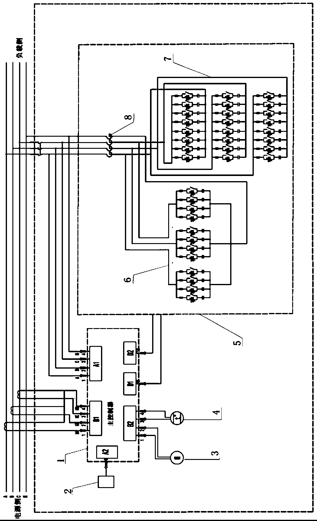
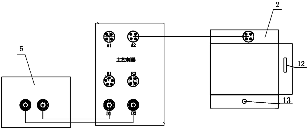
[0021] Such as figure 1 Shown is a schematic diagram of a three-phase capacitance unbalance control device of the present invention. The three-phase capacitance unbalance control device includes a main controller 1, a current acquisition device connected to the input terminal B1 of the main controller 1, and a main The voltage acquisition device connected to the input terminal A1 of the control 1 and the fine reactive power compensation unit 5 connected to the output terminals D1 and D2 of the main controller 1. The current acquisition device and the voltage acquisition device collect the current and voltage values ​​of the three-phase electricity and transmit them Enter the main controller 1 to perform processing calculations, and then control the work of the fine reactive power compensation circuit according to the calculation results. ...


PUM


Abstract

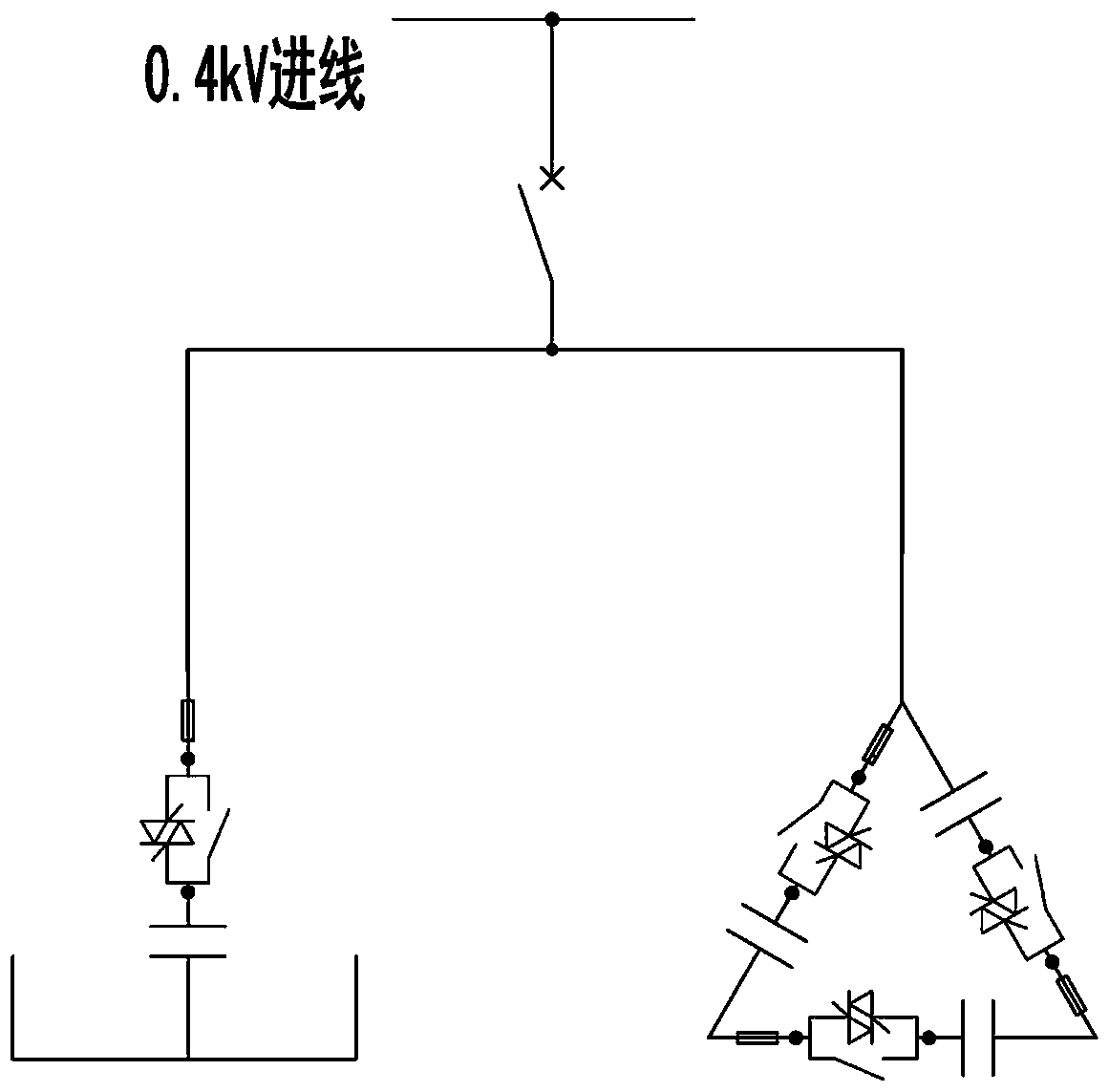
The invention discloses a three-phase unbalance and reactive power control device and method of an interphase capacitor. The three-phase unbalance and reactive power control device of the interphase capacitor comprises a master controller, a current acquisition device, a voltage acquisition device and a fine reactive compensation unit, wherein the current acquisition device and the voltage acquisition device are connected with an input end of the master controller, and the fine reactive compensation unit is connected with an output end of the master controller and comprises an interphase compensation circuit and a phase-zero compensation circuit. The interphase compensation circuit and the phase-zero compensation circuit adopt capacitors to compensate, the unbalance phenomenon of a three-phase power grid can be effectively controlled; with the utilization of capacitor adjustment branches, the inductive reactive power in three-phase electricity can be effectively offset; and moreover, a plurality of capacitor adjustment branches are connected to the three-phase electricity and between the three-phase electricity and a zero line, the adjustment is more fine, and the over-compensation also can be prevented.

Description

Technical field [0001] The present invention relates to the field of three-phase unbalance treatment, in particular to a device and method for three-phase unbalance and reactive power treatment of interphase capacitance. Background technique [0002] With the advancement of society and the development of technology, a large number of power electronic devices have been put into use in the power grid. Although these devices have brought users technical advantages and economic benefits, they have caused serious pollution to the power grid and seriously threatened others. Safe operation of electrical equipment. The pollution caused by these power electronic equipment is mainly divided into the following categories. [0003] Reactive power: Power electronic equipment will absorb a large amount of reactive power from the grid during use, and due to the use of digital control technology, the control accuracy and response time are improved, and the reactive power fluctuates sharply. A la...

Claims


Application Information

Patent Timeline
Patent Type & Authority Patents(China)
IPC IPC(8): H02J3/26H02J3/18H02J13/00H02J3/01
CPCH02J3/01H02J3/18H02J3/26H02J13/00Y02E40/30Y02E40/40Y02E40/50
Inventor 单冠华王山磊曹文华康亚明韩得刚
Owner SHANDONG ELECTRICAL ENG & EQUIP GRP XINNENG TECH CO LTD
Learn More