An incubator for an electric power on-line monitoring device

A technology for monitoring devices and incubators, applied in the direction of measuring devices, measuring electricity, measuring electrical variables, etc., can solve the problems of equipment not working normally, life reduction, high temperature, etc., and achieve low power consumption, good temperature, and high heat dissipation efficiency Effect

Active Publication Date: 2018-06-19
STATE GRID CORP OF CHINA +2
View PDF3 Cites 0 Cited by
  • Summary
  • Abstract
  • Description
  • Claims
  • Application Information

AI Technical Summary

Problems solved by technology

[0004] The purpose of the present invention is to solve the problem that the internal temperature of the incubator of the electric power online monitoring device is too high in summer, which causes the equipment to fail to work normally and the service life is reduced, and proposes an incubator for the electric power online monitoring device

Method used


Image

  • An incubator for an electric power on-line monitoring device
  • An incubator for an electric power on-line monitoring device

Examples


specific Embodiment approach 1

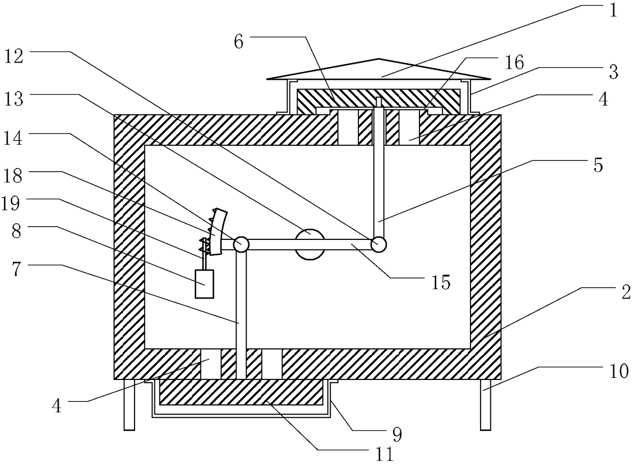
[0020] Embodiment 1: Combining figure 1 Illustrating this embodiment, an incubator for an on-line power monitoring device described in this embodiment includes an incubator body 2;

[0021] It also includes a motor 8, a screw 19, a worm gear 18, a worm gear 15, a lower connecting rod rotating shaft 14, a lower connecting rod 7, a lower heat shield 11, a central rotating shaft 13, an upper connecting rod rotating shaft 12, and an upper connecting rod 5. and the upper heat insulation cap 6;

[0022] The outer side of the top of the incubator body 2 is provided with a shell boss 16, which can prevent the upper flowing water from entering the interior of the incubator body 2 through the ventilation holes 4; the shell boss 16 is provided with N ventilation holes 4, There is also a connecting rod hole on the housing boss 16;

[0023] The bottom of the incubator body 2 is provided with P ventilation holes 4 and another connecting rod hole;

[0024] The upper heat insulating cap 6 ...

specific Embodiment approach 2

[0030] Embodiment 2: This embodiment further defines an incubator for an on-line power monitoring device described in Embodiment 1. In this embodiment, the worm gear 18 is a partial ring, so that the worm gear 18 and the worm gear rod are connected to each other. 15 Fastening is easier and saves weight.

specific Embodiment approach 3

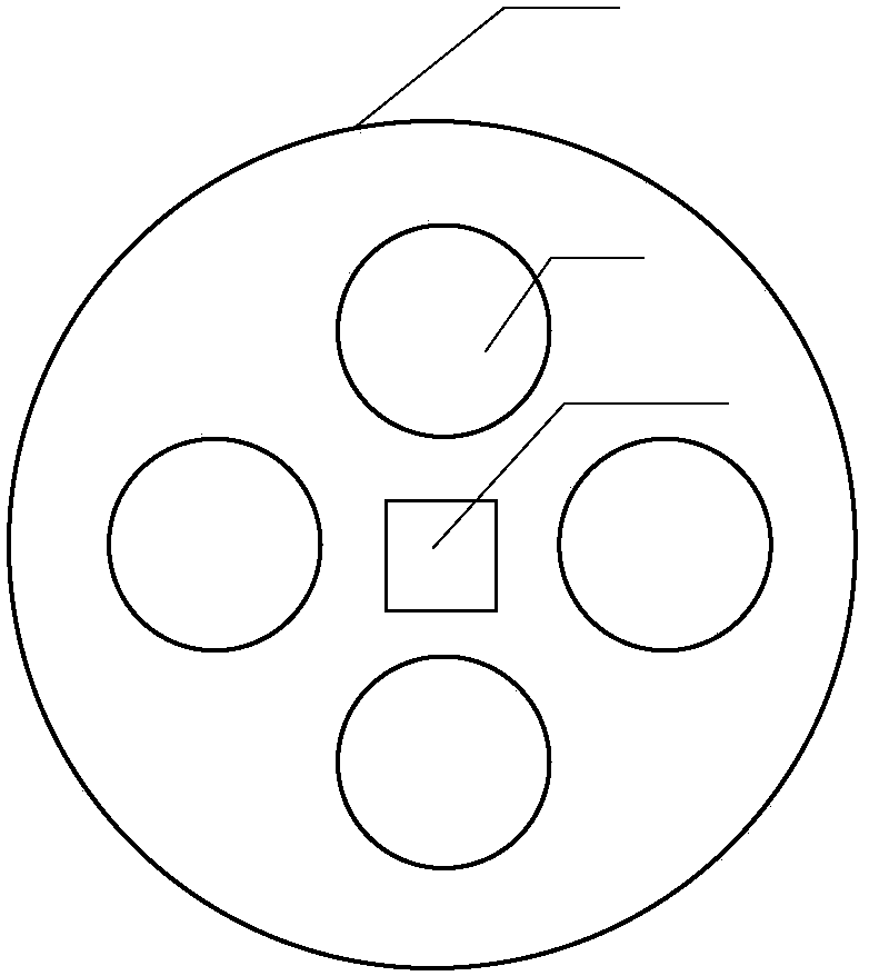
[0031] Specific implementation three: combination figure 2 Describing this embodiment, this embodiment further defines an incubator for an on-line power monitoring device described in Embodiment 1. In this embodiment, the upper surface of the housing boss 16 is circular. It is beneficial to cover the N ventilation holes 4 and the connecting rod holes more easily with the upper heat insulation cap.


PUM


Abstract

The invention relates to a heat preservation box for an electric power online monitoring device to solve the problems that according to a heat preservation box for the electric power online monitoring device, temperature inside the heat preservation box is too high in summer, equipment can not work normally, and service life is shortened.An outer shell boss is arranged on the outer side of the top of a heat preservation box body, and the boss and the bottom are provided with vent holes and connecting rod holes; a motor and a center rotating shaft are fixed into the heat preservation box body; a worm gear rod can rotate around the center rotating shaft, one end of the worm gear rod is connected with one end of an upper connecting rod through an upper connecting rod rotating shaft, the other end of the worm gear rod and the negative camber of a worm gear are fixed together, and the other end of the worm gear rod is connected with one end of a lower connecting rod through a lower connecting rod rotating shaft; the other end of the upper connecting rod and the other end of the lower connecting rod penetrate through the connecting rod holes to be fixed to two heat insulation caps respectively; worm drive is formed by a threaded rod and the worm gear.The heat preservation box has the advantage that the too high temperature in the heat preservation box is effectively prevented.The heat preservation box is suitable for heat preservation of the electric power online monitoring device or heat preservation of other outdoor facilities.

Description

technical field [0001] The invention relates to the technical field of power online monitoring, in particular to an incubator for a power online monitoring device. Background technique [0002] According to statistics, when the power transmission and transformation equipment condition monitoring device operates in a low temperature environment for a long time, there are common phenomena such as high false alarm rate, frequent failures, and heavy maintenance work. , The reliability problem needs to be solved urgently. [0003] Usually, the incubator adopts a closed structure to place the online monitoring device in the incubator. Since the internal monitoring device will generate a certain amount of heat during operation, a certain thickness of insulation layer can be arranged outside the incubator to ensure that under low temperature conditions maintain a certain temperature inside. However, because the online monitoring device is installed outdoors, although the temperatu...

Claims


Application Information

Patent Timeline
Patent Type & Authority Patents(China)
IPC IPC(8): G01R31/00
CPCG01R31/00
Inventor 于春来刘洋朱学成张洪达吴明君王磊张阳
Owner STATE GRID CORP OF CHINA
Why Eureka
Try Eureka