
Level bracket structure and leveling method thereof

A technology of support structure and level gauge, which is applied in the direction of machine platform/support, height/level measurement, instrument, etc., can solve the problems of cumbersome leveling process and low efficiency of the leveling instrument, and achieve the effect of improving adjustment efficiency and simplifying adjustment operation steps

Inactive Publication Date: 2016-07-27
SHANDONG GEO-SURVEYING & MAPPING INST
View PDF5 Cites 8 Cited by
  • Summary
  • Abstract
  • Description
  • Claims
  • Application Information

AI Technical Summary

Problems solved by technology

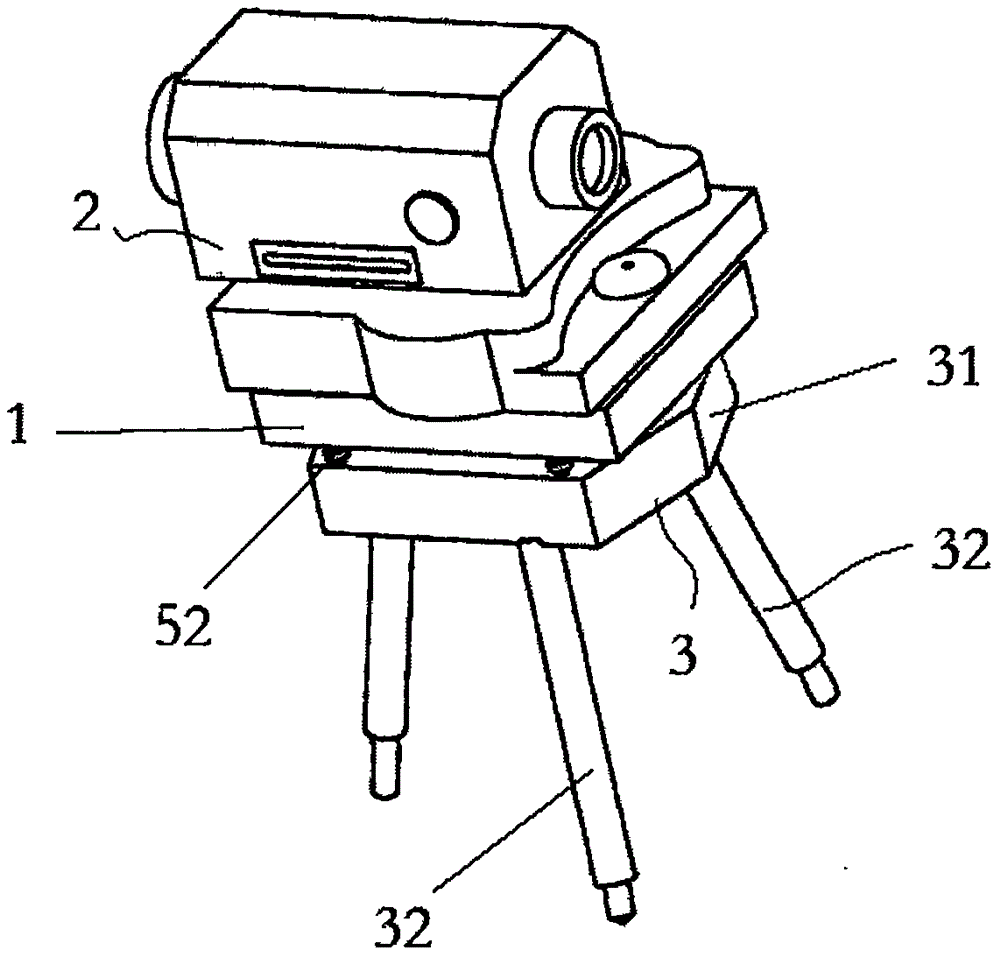
[0005] Therefore, the technical problem to be solved by the present invention is to overcome the technical defects that the leveling process of the leveling instrument is cumbersome and inefficient when the vertical axis has a larger deflection angle than the vertical direction after the tripod is fixed, thereby providing A support structure for a level instrument capable of quickly leveling the level instrument

Method used


Image

  • Level bracket structure and leveling method thereof
  • Level bracket structure and leveling method thereof

Examples


Embodiment 1

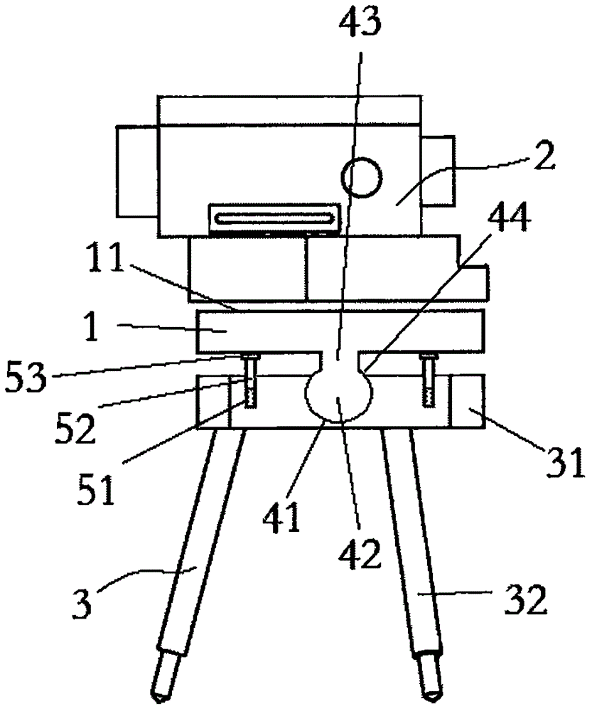
[0046] This embodiment provides a support structure for a level instrument, such as figure 1 and figure 2As shown, it includes: a base plate 1 with a mounting surface 11, on which a vertical axis (not shown) suitable for installing a level 2 is provided on the mounting surface 11, and the vertical axis is perpendicular to the mounting surface 11 The tripod 3 has a top plate 31, and is connected with the top plate 31 and is used to support three legs 32 of the top plate 31; the legs 32 can be fixed-length legs, or adjustable-length legs; the matching structure, It is arranged between the base plate 1 and the top plate 31, and is used to connect the base plate 1 and the top plate 31, so that the base plate 1 can be automatically adjusted when the level gauge 2 is not installed and is not fixed. , and then keep the installation surface 11 horizontal; the adjustable fixing structure is arranged on the top plate 31 and is used to fix the substrate 1 after the installation surface...

Embodiment 2

[0054] This embodiment provides a method for leveling the support structure of the level gauge. figure 1 and figure 2 shown, including the following steps:

[0055] 1) Separate the three legs 32 of the tripod 3, and support the top plate 31 at the target position;

[0056] 2) installing the base plate 1 on the top plate 31 through a matching structure, so that the base plate 1 is automatically adjusted to keep the mounting surface 11 horizontal;

[0057] 3) Adjust the adjustable fixing structure to fix the substrate 1 .

[0058] As a preferred solution, after the step 3, a step is further included: adjusting the adjustable fixing structure again to drive the whole base plate 1 to move vertically upward to a certain height.

[0059] The matching structure includes: a circular groove 41, set on the top plate 31, with a smooth inner wall; a circular protrusion 42, connected with the base plate 1 through a connecting part 43, with a smooth outer wall, used for installation int...


PUM


Abstract

The invention provides a level bracket structure and a leveling method thereof. The bracket structure comprises a substrate, a tripod, a matching structure and an adjustable fixed structure, wherein the substrate has a mounting surface; the mounting surface is provided with a vertical shaft suitable for mounting a level; the vertical shaft is perpendicular to the mounting surface; the tripod has a top plate, and three support legs connected with the top plate and used for supporting the top plate; the matching structure is arranged between the substrate and the top plate, and is used for connecting the substrate with the top plate; when the substrate is not provided with the level and not fixed, the matching structure can automatically adjust to level the mounting surface; and the adjustable fixed structure is arranged on the top plate, and is used for fixing the substrate after automatically adjusting the mounting surface of the substrate levelly. Compared with the prior art, the bracket structure largely simplifies the adjusting operation steps, and can greatly improve the adjusting efficiency.

Description

technical field [0001] The invention relates to the technical field of support structures for surveying instruments, in particular to a leveling instrument support structure and a leveling method thereof. Background technique [0002] Levels are widely used in construction engineering and other fields, and are generally used to measure the height of a certain point or the height difference between two points. Existing optical level measuring instruments are usually composed of a level, a tripod and two leveling rods. The tripod is provided with a vertical axis, and the level is rotatably sleeved on the vertical axis. The level is equipped with an objective lens, an eyepiece 1. For telescopes composed of collimating lenses and reticles, the level is also equipped with a corresponding leveling structure, so that the collimation axis of the telescope can be adjusted to a horizontal state during measurement. The leveling structure mainly includes a circular level set on the lev...

Claims


Application Information

Patent Timeline
Patent Type & Authority Applications(China)
IPC IPC(8): F16M11/22F16M11/24F16M11/14F16M11/18G01C5/00
CPCF16M11/2078F16M11/14F16M11/18F16M11/22F16M11/24G01C5/00
Inventor 刘同文王慧敏
Owner SHANDONG GEO-SURVEYING & MAPPING INST
Learn More