
A Computer Graphics Recognition Method for Mesostructure of Composite Materials

A technology of computer graphics and mesostructure, applied in the direction of calculation, pattern design device, special data processing application, etc., can solve problems such as the difficulty of identifying the mesostructure of composite materials, and achieve the effect of reducing workload and avoiding influence

Active Publication Date: 2017-08-04
NANJING UNIV OF AERONAUTICS & ASTRONAUTICS
View PDF2 Cites 0 Cited by
  • Summary
  • Abstract
  • Description
  • Claims
  • Application Information

AI Technical Summary

Problems solved by technology

[0006] Aiming at the deficiencies of the above-mentioned prior art, the purpose of the present invention is to provide a computer graphic recognition method for the mesostructure of composite materials, to solve the problem that it is very difficult to identify the mesostructure of composite materials in the prior art. The method of the present invention Without manual intervention, a 3D model of the mesostructure of composite materials can be established, and the warp, weft and matrix can be automatically identified by the computer

Method used


Image

  • A Computer Graphics Recognition Method for Mesostructure of Composite Materials
  • A Computer Graphics Recognition Method for Mesostructure of Composite Materials
  • A Computer Graphics Recognition Method for Mesostructure of Composite Materials

Examples


Embodiment Construction

[0026] In order to facilitate the understanding of those skilled in the art, the present invention will be further described below in conjunction with the embodiments and accompanying drawings, and the contents mentioned in the embodiments are not intended to limit the present invention.

[0027] A method for computer graphics recognition and three-dimensional model modeling of composite material mesostructure of the present invention comprises the following steps:

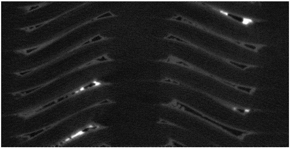
[0028] Step 1, using X-ray computerized tomography technology (abbreviated as XCT technology) to obtain the mesostructure picture of the 2.5-dimensional ceramic matrix composite material, the out-of-plane direction of the mesostructure picture is parallel to the axial direction of the weft yarn, and the length direction of the picture is parallel to the length of the material, such as figure 1 shown.

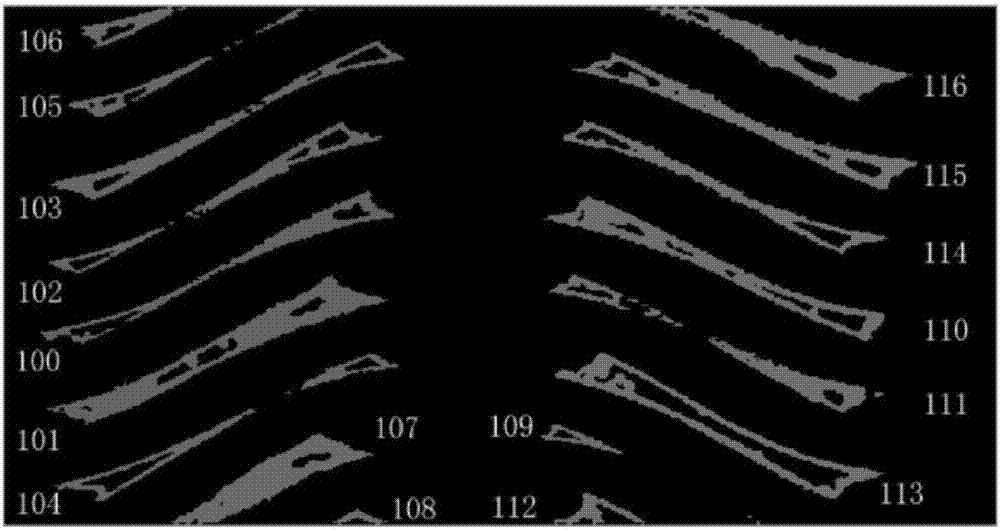
[0029] Step 2. Use threshold segmentation to identify the ceramic substrate, and number the independent substrat...


PUM


Abstract

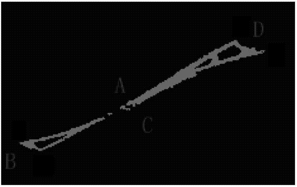
The invention discloses a computer pattern recognition method for the composite material microstructure. The computer pattern recognition method includes the following steps that pictures of the 2.5-dimensional composite material microstructure are obtained; matrix areas are recognized with the threshold segmentation technology; all the matrix areas serve as twisty quadrilateral structures to be treated, and four boundaries of each matrix area are recognized and marked; the matrix areas matched with the left matrix areas are found; the complete boundaries of warp yarn areas are obtained in a spline fitting mode; in all pairs of symmetrical matrix areas, the areas defined by the boundaries of the left matrix areas, the boundaries of the right matrix areas, upper warp yarn boundary lines and lower warp yarn boundary lines are weft yarn areas, and recognition of components is completed; all the recognized pictures are stacked to build a three-dimensional model of the 2.5-dimensional inside microstructure. According to the computer pattern recognition method, manual intervention is avoided, the three-dimensional model of the composite material microstructure can be built, and warp yarns, weft yarns and matrixes can be automatically recognized by a computer.

Description

technical field [0001] The invention belongs to the technical field of composite materials, and in particular refers to a method for computer graphic recognition and three-dimensional model modeling of a 2.5-dimensional composite material mesostructure. Background technique [0002] 2.5D fiber-reinforced composite materials have the characteristics of high specific stiffness, specific strength, and good anti-delamination properties, and are widely used in military, energy, transportation and other industries. The identification of mesostructure is an important link in the structural design of 2.5D composite materials. The mesoscopic identification process generally uses non-destructive testing methods to obtain digital images of the mesoscopic structure of materials, and then identifies various component structures through computer technology. Based on it, the mesoscopic mechanical model of the material can be established, the mechanical properties and damage calculation of...

Claims


Application Information

Patent Timeline
Patent Type & Authority Patents(China)
IPC IPC(8): G06F17/50D03C19/00
CPCD03C19/005
Inventor 高希光宋迎东于皓韩笑
Owner NANJING UNIV OF AERONAUTICS & ASTRONAUTICS
Learn More