
Modular reverse shoulder orthopaedic implant and method of implanting the same

An orthopaedic, inversion technique, used in joint implants, joint implants, shoulder joints, etc., to solve problems such as joint instability and pain

Active Publication Date: 2016-07-27
DEPUY SYNTHES PROD INC
View PDF8 Cites 6 Cited by
  • Summary
  • Abstract
  • Description
  • Claims
  • Application Information

AI Technical Summary

Problems solved by technology

[0003] However, in some cases, the patient's natural shoulder (including its soft tissues) has deteriorated to the point where the joint is unstable and painful

Method used


Image

  • Modular reverse shoulder orthopaedic implant and method of implanting the same
  • Modular reverse shoulder orthopaedic implant and method of implanting the same
  • Modular reverse shoulder orthopaedic implant and method of implanting the same

Examples


Embodiment Construction

[0029] While the inventive concept is susceptible to various modifications and alternative forms, specific exemplary embodiments of the invention have been shown by way of example in the drawings and will be described in detail herein. It should be understood, however, that there is no intent to limit inventive concepts to the particular forms disclosed, but on the contrary, the intention is to cover all modifications, equivalents, and alternatives falling within the spirit and scope of the invention.

[0030] Terms denoting anatomical references (eg, anterior, posterior, medial, lateral, superior, inferior, etc.) may be used throughout this disclosure to refer to both the orthopedic implants described herein and the patient's natural anatomy. These terms have well-known meanings both in the study of anatomy and in the fields of orthopedic surgery. Such anatomical reference terms used in the specification and claims are intended to be accorded their commonly understood meaning...


PUM


Abstract

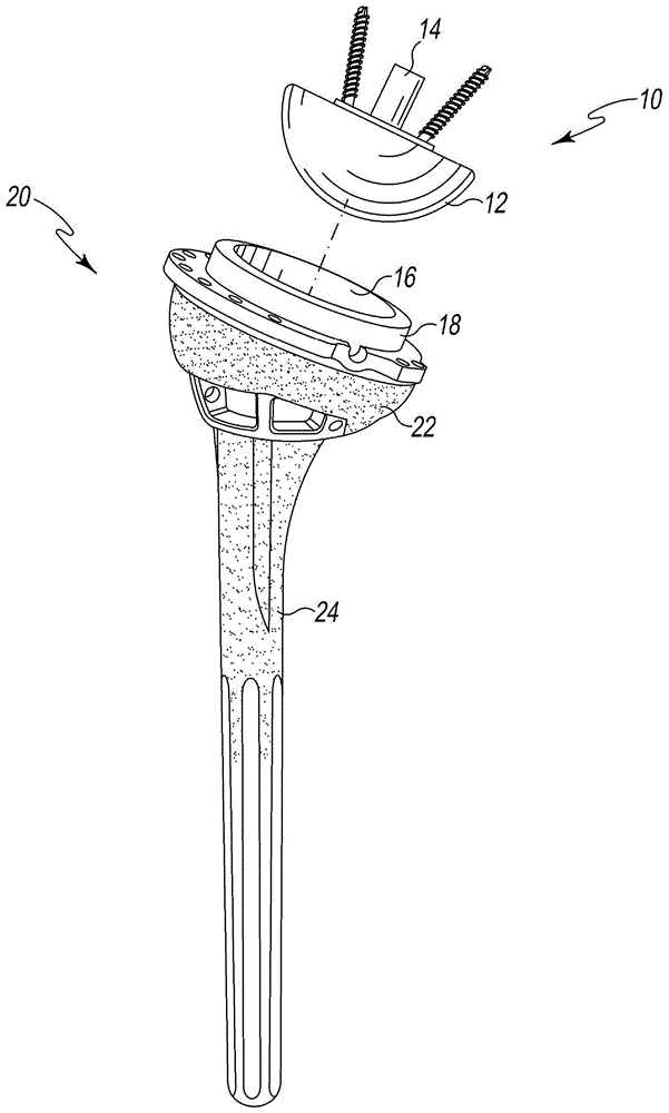
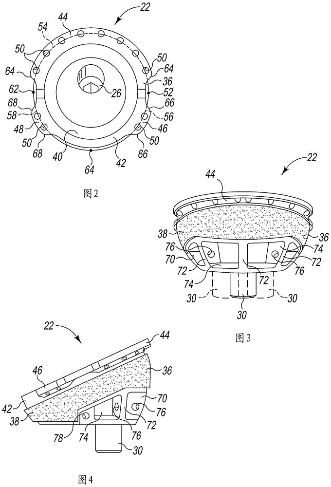
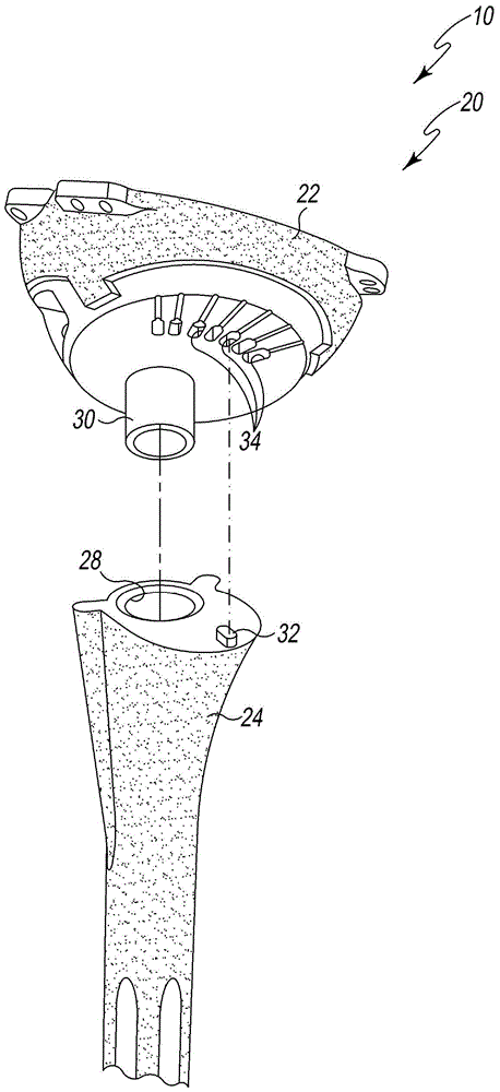
The present invention discloses a modular reverse shoulder orthopaedic implant and a method of implanting the same. A modular reverse shoulder orthopaedic implant includes a humeral stem component and a separable fracture epiphysis component having a number of suture holes formed therein. The fracture epiphysis component is configured to receive a number of sutures for surgically repairing a proximal humeral fracture.

Description

technical field [0001] The present disclosure relates generally to orthopedic implants, and more particularly to inverted shoulder orthopedic implants. Background technique [0002] During the patient's lifetime, total shoulder replacement surgery may be required on the patient due to, for example, disease or trauma. In total shoulder replacement surgery, a humeral prosthesis is used to replace the natural head of the patient's humerus. A humeral prosthesis typically includes an elongated stem member implanted in the intramedullary canal of the patient's humerus and a hemispherical prosthetic head member secured to the stem member. In such total shoulder replacement surgery, the natural glenoid surface of the scapula is reconstructed or or otherwise replaced with a glenoid component that provides a bearing surface on which the prosthetic head component of the humerus prosthesis can rest. Joint movement is performed on the surface. [0003] However, in some cases, the pati...

Claims


Application Information

Patent Timeline
Patent Type & Authority Applications(China)
IPC IPC(8): A61F2/40A61F2/30
CPCA61F2/4014A61F2/4059A61F2002/30331A61F2002/30507A61F2002/30604A61F2002/3082A61F2/4081A61F2002/30199A61F2002/4011A61F2002/30884A61F2002/4022A61F2002/4037A61F2002/4044A61F2002/4074A61B17/842A61B17/72A61B17/68A61F2002/30433A61F2002/30461
Inventor J.查瓦里亚D.T.托德D.彭塞特
Owner DEPUY SYNTHES PROD INC
Learn More