control switch assembly

A technology for controlling switches and components, which is applied in the direction of electric switches, electrical components, circuits, etc., and can solve problems such as component damage and device damage

Active Publication Date: 2017-10-20
WISTRON NEWEB
View PDF3 Cites 0 Cited by
  • Summary
  • Abstract
  • Description
  • Claims
  • Application Information

AI Technical Summary

Problems solved by technology

However, this type of switch only allows authorized personnel to perform simple settings on the device. If you want to perform more complicated settings, such as switching the operating mode or adjusting the settings of the use parameters, you need to destroy the device
In this way, the components inside the device will be damaged by the influence of ambient moisture

Method used


Image

  • control switch assembly
  • control switch assembly
  • control switch assembly

Examples


Embodiment Construction

[0049] In order to make the purpose, features and advantages of the present invention more comprehensible, the following specific examples are given together with the accompanying drawings for a detailed description. Wherein, the configuration of each element in the embodiment is for illustration, not for limiting the present invention. Moreover, part of the reference numerals in the embodiments is repeated, for the sake of simplicity of description, it does not imply the correlation between different embodiments.

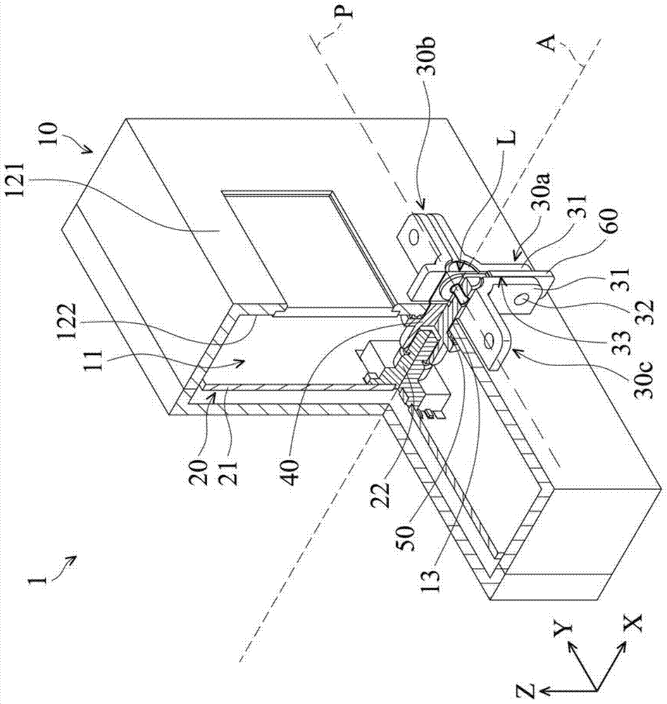
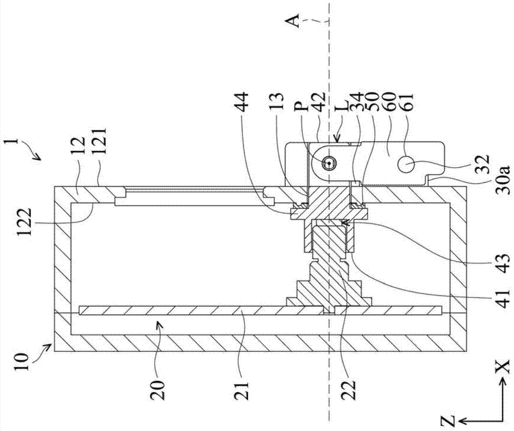
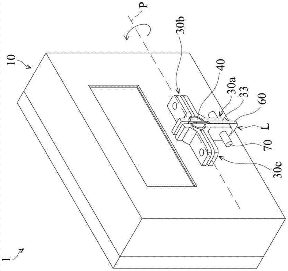
[0050] Please also refer to figure 1 and figure 2 , which shows a schematic cross-sectional view of the control switch assembly 1 according to the embodiment of the present invention. The control switch assembly 1 is suitable for combining with a device (eg water meter, electricity meter) and is configured to adjust the settings of the device. In the embodiment, the control switch assembly 1 includes a housing 10 , a control module 20 , a plurality of positioni...


PUM


Abstract

The invention discloses a control switch assembly, which includes a casing, a control module, a link mechanism, and a plurality of positioning units. The casing defines an accommodating space and has an opening. The control module is arranged in the accommodating space and has a knob that can rotate around a main shaft, wherein the main shaft passes through the opening. The link mechanism passes through the opening and is connected to the knob in a manner that can move relative to the knob. The positioning units are located at the edge of the opening and are spaced apart from each other, radiate outward with the main axis as the center, and protrude upward along the main axis. The linkage mechanism can rotate the pulling knob to change the action of the control module, and can selectively connect one of the plurality of positioning units.

Description

technical field [0001] The invention relates to a control switch assembly which can be used to adjust the settings of a device, in particular to a control switch assembly with waterproof and anti-disassembly functions. Background technique [0002] Devices installed in fixed locations on the market (eg, water meters, electricity meters) usually have switches for authorized personnel to set the functions of the devices. In addition, in order to prevent the device from being deliberately adjusted by interested persons, the device is usually placed in a protective cover. The surroundings of the protective cover are sealed with multiple bolts, and the bolts are pierced with lead seals to achieve the purpose of anti-demolition. However, the arrangement of the above-mentioned protective cover will result in an increase in volume, and disadvantageously reduce the cost. [0003] In order to solve the above problems, some devices are equipped with a switch with anti-tampering funct...

Claims


Application Information

Patent Timeline
Patent Type & Authority Patents(China)
IPC IPC(8): H01H19/10H01H19/06H01H19/03H01H19/02
Inventor 洪天均张仁勇
Owner WISTRON NEWEB
Why Eureka
Try Eureka