
Laser ranging method and device based on synchronous sampling and multiple phase measurement

A technology of laser ranging and multiple phases, which is applied in the direction of measuring devices, radio wave measuring systems, electromagnetic wave re-radiation, etc., can solve the problems of prolonging the ranging time, achieve the extension of the ranging time, the method is simple and efficient, and the distance measurement is improved The effect of precision

Inactive Publication Date: 2016-07-20
SHANGHAI INST OF TECHNICAL PHYSICS - CHINESE ACAD OF SCI
View PDF7 Cites 16 Cited by
  • Summary
  • Abstract
  • Description
  • Claims
  • Application Information

AI Technical Summary

Problems solved by technology

This method uses clock counting with a large dynamic range to obtain coarse-range data, which solves the ambiguity problem when the target distance exceeds the measurement distance of a single modulation cycle, so that the modulation frequency is no longer restricted by the measurement range, and can be increased as much as possible to improve Ranging accuracy; on the other hand, in order to achieve accurate phase measurement of the echo signal, the method of oversampling and fast frequency domain phase detection is used to measure the phase of the echo multiple times, which improves the ranging time without prolonging the ranging time. precision

Method used


Image

  • Laser ranging method and device based on synchronous sampling and multiple phase measurement
  • Laser ranging method and device based on synchronous sampling and multiple phase measurement
  • Laser ranging method and device based on synchronous sampling and multiple phase measurement

Examples


Embodiment Construction

[0038] The technical solutions in the embodiments of the present invention will be described in detail below in conjunction with the accompanying drawings in the embodiments of the present invention. Obviously, the described embodiments are only some of the embodiments of the present invention, not all of them. Based on the embodiments of the present invention, all other embodiments obtained by persons of ordinary skill in the art without making creative efforts belong to the protection scope of the present invention.

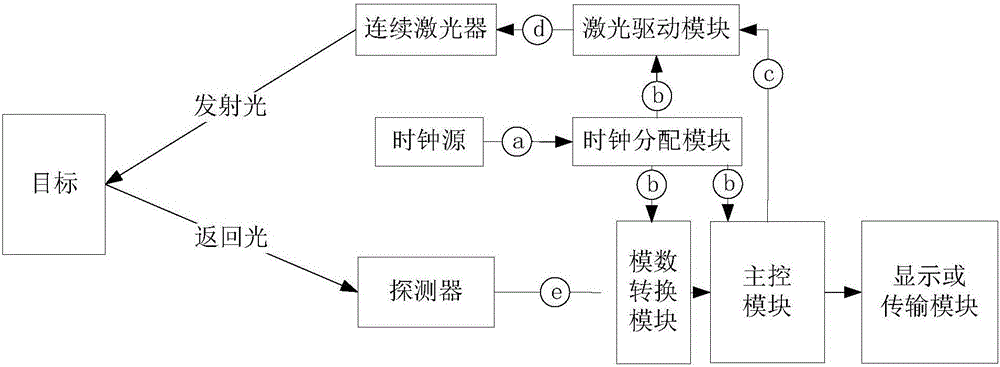
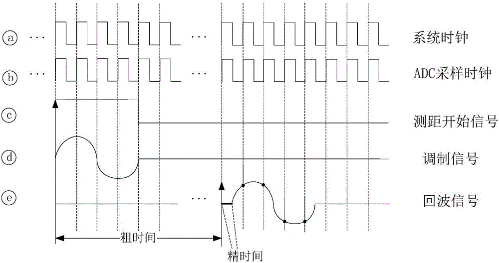
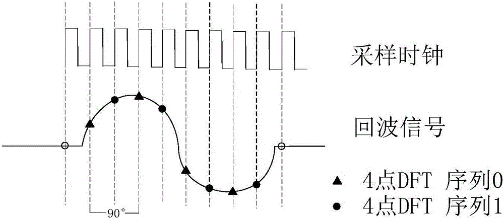
[0039] The system implementation example of the method of the present invention is as figure 1As shown, the clock source provides a high-precision global clock, which is distributed to the main control module, laser driver module and analog-to-digital conversion module by the clock distribution module; the main control module sends a start signal to the laser driver module when a distance measurement starts , the latter generates a sinusoidal signal whose perio...


PUM


Abstract

The invention discloses a laser ranging method and a laser ranging device based on synchronous sampling and multiple phase measurement. A system sends out a starting signal so that a laser device driving unit generates a semicontinuous sinusoidal signal with period being integral multiples of a global clock, the semicontinuous sinusoidal signal is used for modulating intensity of emitted laser, echo light reflected by a target is converted into an electric signal and then sampled by an analog-to-digital converter driven by the global clock, and a modulation frequency and a sampling interval are in a homologous frequency multiplication relationship. Number of the global clocks between a rising edge of the starting signal to a previous moment of a first echo waveform sampling point is recorded to obtain a rough distance, the sampled digital waveforms are subjected to Fourier transform, phase difference between echo sinusoidal waveform to a previous moment of its arrival is obtained by utilizing frequency domain phase discrimination, multiple phase measurement is carried out on echoes after adopting oversampling and series decomposition to increase precision, the average of phase measurement results is converted into precise distance according to a sinusoidal modulation period, and distance information is derived by adding the rough distance to the precise distance. The laser ranging method and the laser ranging device have the advantages of being free of ranging distance limitation, easy hardware implementation and the like.

Description

Technical field: [0001] The invention relates to the field of laser ranging signal processing, in particular to a phase-based laser ranging method and system based on synchronous sampling and multiple phase measurements. Background technique: [0002] Laser ranging is a major aspect of the application of laser technology. Due to the advantages of high coherence, directivity, and monochromaticity of laser, the laser ranging system can realize long-distance and high-precision ranging functions. Phase method laser ranging is an important type of laser ranging system. This method indirectly measures the propagation time of the optical signal by measuring the phase change produced by the continuous modulation signal propagating back and forth between the laser source and the target, and then obtains the measured value. measured distance. This method can achieve high ranging accuracy through high-frequency modulation of the output optical signal and precise measurement of the ech...

Claims


Application Information

Patent Timeline
IPC IPC(8): G01S17/32G01S17/36
CPCG01S17/32G01S17/36
Inventor 吴小可徐卫明舒嵘肖琳
Owner SHANGHAI INST OF TECHNICAL PHYSICS - CHINESE ACAD OF SCI
Learn More