Power generation device for energy saving illumination

A power generation device and energy-saving lighting technology, which is applied to lighting devices, components of lighting devices, circuit layout, etc., and can solve problems such as inability to generate electricity

Inactive Publication Date: 2016-07-20
ZHEJIANG UNIV
View PDF5 Cites 7 Cited by
  • Summary
  • Abstract
  • Description
  • Claims
  • Application Information

AI Technical Summary

Problems solved by technology

[0003] The present invention provides a power generation device for energy-saving lighting, aiming to solve the problem that the water flowing out of the existing faucet cannot generate electricity

Method used


Image

  • Power generation device for energy saving illumination
  • Power generation device for energy saving illumination
  • Power generation device for energy saving illumination

Examples


Embodiment 1

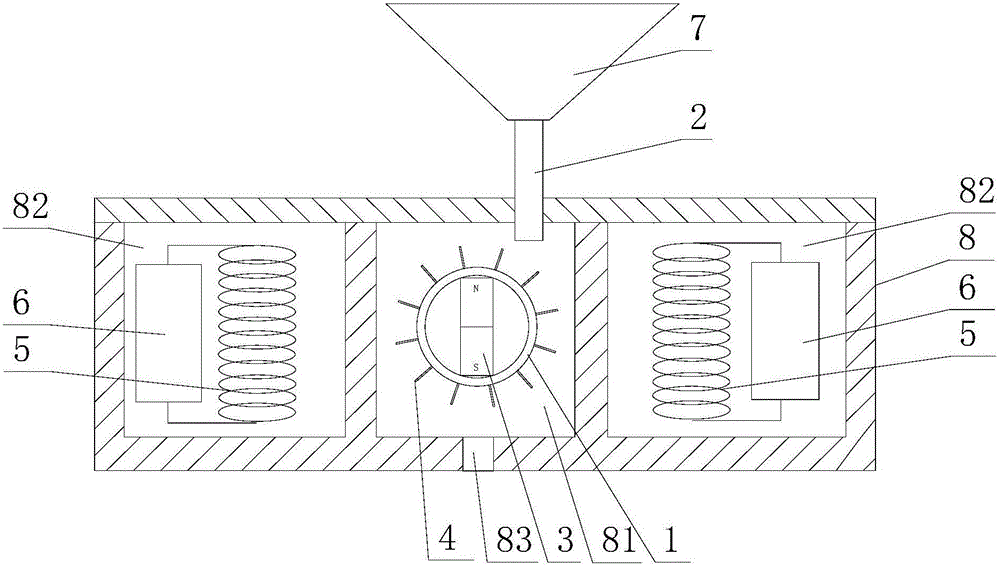
[0017] refer to figure 1 , a power generation device for energy-saving lighting obtained by the method of claim 2, comprising a rotating wheel 1, a water pipe 2, a permanent magnet 3, a coil 5 and a No. 1 storage battery 6, the coil 5 is arranged around the rotating wheel 1 and Located in the radial direction of the rotating wheel 1, the permanent magnet 3 is strip-shaped, and the permanent magnet 3 is fixed on the rotating wheel 1, and the outer ring of the rotating wheel 1 is evenly distributed with blades 4; the water ejected from the water pipe 2 rushes towards the blade 4, thereby The rotating wheel 1 is driven to rotate, and the coil 5 cuts the lines of magnetic induction to generate electric energy and store it in the No. 1 storage battery 6 . The power generation device also includes a washbasin 7 and an accommodation tank 8 located below the washbasin 7, and the water pipe 2 is a drain pipe connected between the washbasin 7 and the accommodation tank 8; the accommodat...

Embodiment 2

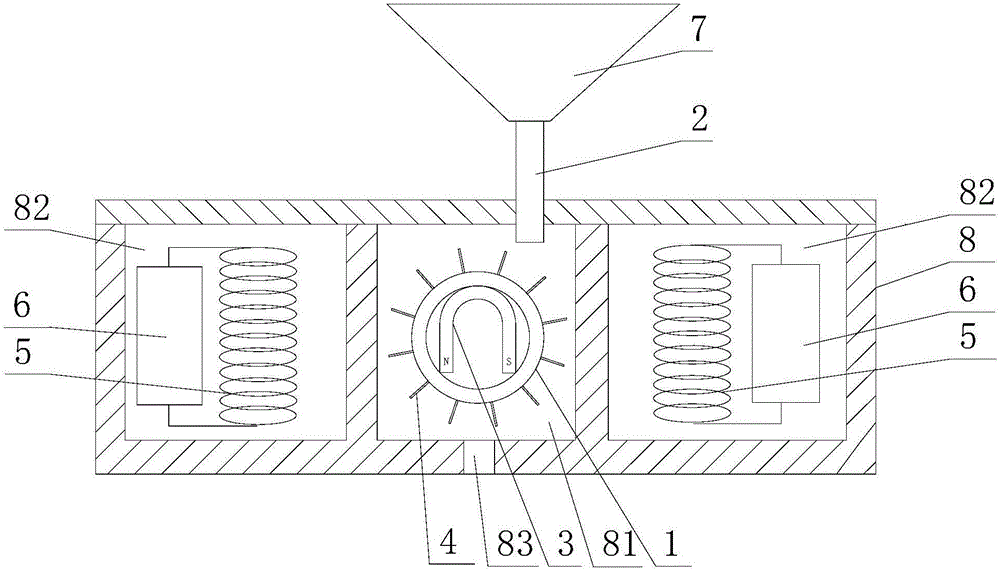
[0020] refer to figure 2 , the difference from Embodiment 1 is that the permanent magnet 3 is horseshoe-shaped.

Embodiment 3

[0022] refer to image 3 , and the difference with the second embodiment is that: No. 2 storage battery 9 is provided in the isolation chamber 82, and the power generation sheet 10 made of piezoelectric material is provided at the bottom of the water chamber 81, and the generation sheet 10 is connected with the No. 2 storage battery 9 , The power generating sheet 10 is provided with a circular hole communicating with the drainage hole 83 .

[0023] Working principle: the water flows from the washbasin 7 through the water pipe 2, and the rotating wheel 1 is driven to rotate through the blade 4, and the rotating wheel 1 drives the permanent magnet 3 to rotate, and the coil 5 cuts the magnetic induction line to generate electric energy and stores it in the battery 6; the water flows through After the blade 4 lands on the generating sheet 10, the mechanical energy of the water flow is converted into the electric energy of the generating sheet 10 and stored in the second storage ba...


PUM


Abstract

The invention provides a power generation device for energy saving illumination, and aims to solve the problem that water flowing out from a traditional tap cannot generate electricity. The power generation device comprises a rotating wheel, a water pipe, a permanent magnet, a coil and an accumulator 1; the coil is arranged around the rotating wheel; the permanent magnet is strip-shaped or horseshoe-shaped, and is fixed on the rotating wheel; blades are uniformly distributed on the outer circle of the rotating wheel; water sprayed by the water pipe dashes to the blades so as to drive the rotating wheel to rotate; the coil cuts a magnetic induction line to generate electric energy; the the electric energy is stored in the accumulator 1. The water drained by the water pipe is used for driving the rotating wheel to rotate, and the rotating wheel drives the permanent magnet to rotate, so that the energy is saved. An illumination system comprises a circuit system connected with the accumulator; and the circuit system is provided with an illumination lamp and an adjusting switch for adjusting the brightness of the illumination lamp. The electric quantity in the accumulator is insufficient at times, the brightness adjusting switch can be used for reducing the power consumption, so that the illumination time is prolonged.

Description

technical field [0001] The invention relates to a power generating device, in particular to a power generating device for energy-saving lighting. Background technique [0002] At present, when using water, the water flowing out of the faucet will flow away along the drainpipe after washing hands, which wastes the energy generated by the water flowing from top to bottom. At present, there is no power generation device that utilizes the water flowing out of the faucet to generate electricity. Most of the public toilets are dark and require lighting 24 hours a day, which consumes a lot of electricity. In addition, the water consumption in the toilets is huge, and the water flow is constantly lost. The energy generated by the water flow cannot be used, resulting in great waste; After washing with water, it is of great significance to generate electricity. Contents of the invention [0003] The invention provides a power generation device for energy-saving lighting, aiming at ...

Claims


Application Information

Patent Timeline
IPC IPC(8): F21S9/02F21S9/04F21V23/00F21V23/04
CPCF21S9/02F21S9/046F21V23/023F21V23/04
Inventor 冀瑜邱清盈冯培恩
Owner ZHEJIANG UNIV
Why Eureka
Try Eureka