
Fan case and fan unit

A fan casing and ventilation channel technology, which is applied to pump devices, components of pumping devices for elastic fluids, non-variable-capacity pumps, etc. Effect

Active Publication Date: 2020-09-15
SANYO DENKI CO LTD
View PDF1 Cites 0 Cited by
  • Summary
  • Abstract
  • Description
  • Claims
  • Application Information

AI Technical Summary

Problems solved by technology

In addition, there are cases where the size of the ventilation passage of the fan case is limited due to driving parts such as a motor, and the performance of the motor, etc. is fixed

Method used


Image

  • Fan case and fan unit
  • Fan case and fan unit
  • Fan case and fan unit

Examples


Embodiment Construction

[0042] In the following detailed description, for purposes of explanation, numerous specific details are set forth in order to provide a thorough understanding of the disclosed embodiments. It may be evident, however, that one or more embodiments may be practiced without these specific details. In other instances, well-known structures and devices are shown schematically in order to simplify the drawings.

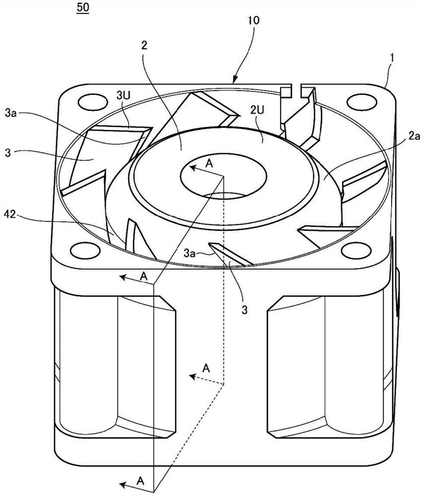
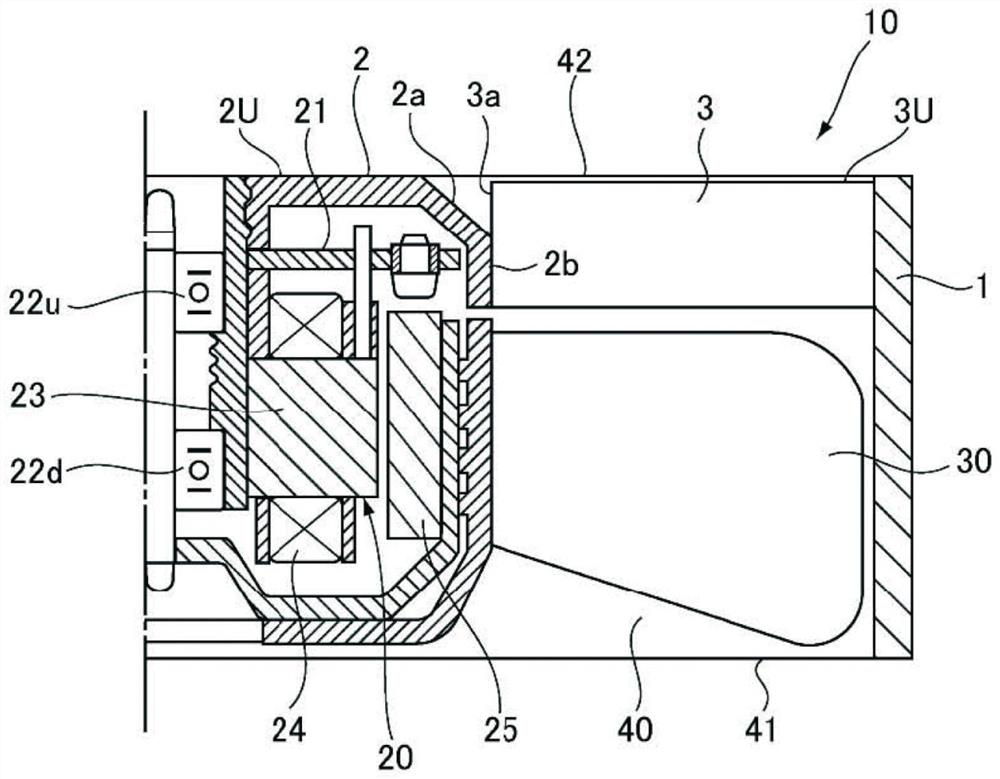
[0043] One embodiment of the present invention will be described below. figure 1 It is a perspective view of the fan device 50 which is an axial flow fan. figure 2 to represent figure 1 The cross-sectional explanatory drawing of the A-A cross-section in .

[0044] The fan device 50 includes at least a motor 20 , a rotor blade 30 for sending air, and a fan case 10 surrounding the motor 20 and the rotor blade 30 .

[0045] The fan casing 10 has ventilation channels 40 . The ventilation passage 40 communicates with an air suction port 41 and an air discharge port 42 . T...


PUM


Abstract

A fan casing includes: an air duct communicating with an air inlet and outlet; a frame body forming an outer peripheral surface of the air duct; a hub portion forming an inner peripheral surface of the air duct on the outlet side; and a stator blade portion provided in the air duct, the stator blade portion coupling the frame body to the hub portion. The hub portion includes a cylindrical-shaped cylindrical portion and a tapered portion provided next to the cylindrical portion and provided in such a manner as to increase the width of the air duct toward the outlet. The stator blade portion couples the cylindrical portion to the frame body.

Description

technical field [0001] Embodiments of the present invention relate to a fan case and a fan device including the fan case. Background technique [0002] In recent years, a so-called axial flow fan unit as described in Japanese Patent Application Laid-Open No. Hei 5-133398 has been widely used as a fan for cooling electronic equipment such as servers. The axial flow fan device sends air into the ventilation passage by rotating the rotor blade portion supported by the motor shaft in the ventilation passage of the fan case. [0003] For such a fan device, it has been proposed to improve the air volume performance. In addition, there are cases where the size of the ventilation passage of the fan case is limited due to a driving part such as a motor, and the performance of the motor or the like is fixed. In this case, it is difficult to improve the air volume performance beyond the limitation of the size of the ventilation passage of the fan case and the like. [0004] Here, in...

Claims


Application Information

Patent Timeline
Patent Type & Authority Patents(China)
IPC IPC(8): F04D29/52F04D25/08
CPCF04D25/08F04D29/522F04D19/002F04D25/0613F04D29/542F04D29/545F04D29/325F04D29/547F04D29/644
Inventor 稻田直哉大澤穗波
Owner SANYO DENKI CO LTD
Learn More