
Centrifugal heat dissipation fan

A cooling fan, centrifugal technology, applied in the field of centrifugal cooling fans, can solve problems such as difficult to control air flow, insufficient wind pressure, large blade air gap, etc., and achieve the effect of improving operating efficiency

Pending Publication Date: 2021-10-22
ACER INC
View PDF7 Cites 0 Cited by
  • Summary
  • Abstract
  • Description
  • Claims
  • Application Information

AI Technical Summary

Problems solved by technology

However, because the appearance of the notebook computer tends to be thinner and thinner and does not like too many cooling holes, the thermal resistance of the system is relatively large, which in turn reduces the air suction of the cooling fan, and makes it difficult for the air from the external environment to enter the system to generate the heat required for heat dissipation. heat convection
[0003] At the same time, the air gap between the blades of the existing centrifugal fan is large, so it is difficult to control the air flow and easily cause backflow, so that the wind pressure is insufficient, thereby affecting the heat dissipation efficiency
Furthermore, once the air inlet is increased to increase the air intake, if the fan blades do not provide a corresponding structure, it is easy to cause air leakage and the like.

Method used


Image

  • Centrifugal heat dissipation fan
  • Centrifugal heat dissipation fan
  • Centrifugal heat dissipation fan

Examples


Embodiment Construction

[0017] Reference will now be made in detail to the exemplary embodiments of the present invention, examples of which are illustrated in the accompanying drawings. Wherever possible, the same reference numbers will be used in the drawings and description to refer to the same or like parts.

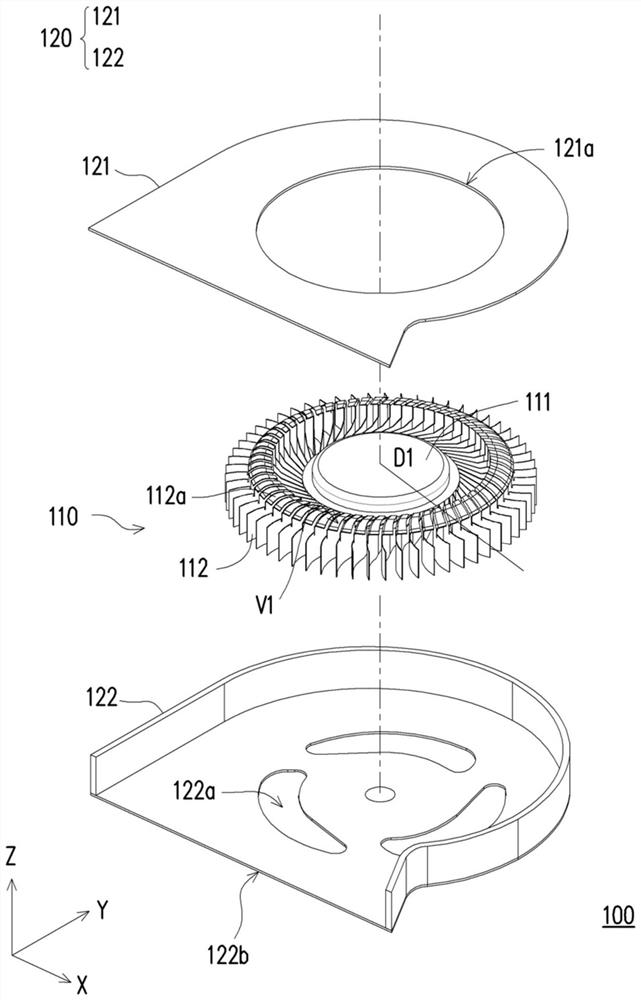
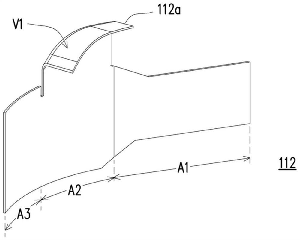
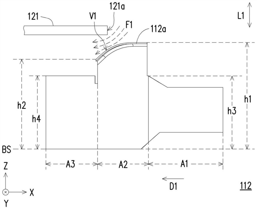
[0018] figure 1 It is an exploded view of a centrifugal cooling fan according to an embodiment of the present invention. Figure 2A yes figure 1 perspective view of the blades of a centrifugal cooling fan. Figure 2B yes figure 1 A partial side view of a centrifugal cooling fan. Cartesian coordinates X-Y-Z are also provided here to facilitate component description. Please also refer to figure 1 and Figure 2A , Figure 2B , in this embodiment, the centrifugal cooling fan 100 includes a housing 120 and an impeller 110 . The casing 120 is composed of a base 122 and a top plate 121, and the casing 120 has air inlets 122a, 121a. Here, the air inlets 121a and 122a of the casing 120 bel...


PUM


Abstract

A centrifugal heat dissipation fan including a housing and an impeller is provided. The housing has at least one flow inlet. The impeller assembled in the housing and rotating about an axial direction includes a hub and a plurality blades disposed around the hub. The flow inlet is located in the axial direction and faces the hub. Each of the blades has a wing tab next to the flow inlet, and the wing tab extends from a main surface of the blade to another blade. The wing tab has an inclined surface facing toward a periphery of the flow inlet along a radial direction of the impeller.

Description

technical field [0001] The invention relates to a cooling fan, in particular to a centrifugal cooling fan. Background technique [0002] Generally speaking, in order to improve the heat dissipation effect in the notebook computer, it is nothing more than to reduce the thermal resistance of the system or to increase the efficiency of the heat dissipation fan in the notebook computer. However, because the appearance of the notebook computer tends to be thinner and thinner and does not like too many cooling holes, the thermal resistance of the system is relatively large, which in turn reduces the air suction of the cooling fan, and makes it difficult for the air from the external environment to enter the system to generate the heat required for heat dissipation. Thermal convection. [0003] At the same time, the air gap between the blades of the existing centrifugal fan is relatively large, so it is difficult to control the airflow and easily cause backflow, resulting in insuf...

Claims


Application Information

Patent Timeline
Patent Type & Authority Applications(China)
IPC IPC(8): F04D25/08F04D29/28F04D29/30G06F1/20
CPCF04D25/08F04D29/281F04D29/30G06F1/203F04D29/282F04D29/162F04D17/08F04D29/4213
Inventor 陈宗廷廖文能谢铮玟林育民柯召汉林光华
Owner ACER INC
Learn More