
Device for automatically counting express items on conveyor

An automatic counting and conveyor technology, applied in conveyor control devices, conveyor objects, conveyors, etc., can solve the problems of high installation and use costs, high environmental requirements, and high costs, and achieve easy installation and maintenance. Low environmental requirements , the effect of strong applicability

Active Publication Date: 2016-07-20
SHENZHEN SEAGEN TECH
View PDF6 Cites 1 Cited by
  • Summary
  • Abstract
  • Description
  • Claims
  • Application Information

AI Technical Summary

Problems solved by technology

This method performs software recognition based on visual images. If the image quality is not good or the express shipments are placed too close together, there will be data error problems, and manual intervention is often required in actual use.
[0004] Both barcode automatic equipment and visual automatic equipment have limitations such as high installation and use costs and high environmental requirements (ground, space, lighting, etc.)
From a technical point of view, whether it is barcode recognition or visual recognition, there is a problem of recognizing the depth of field. Generally, a single device can achieve a depth of field of 0-60cm at most, and the cost is very high, and it is impossible to count some high-level express items.
The barcode recognition technology with a wide range of depth of field is basically monopolized by foreign countries, which leads to high cost of barcode automatic equipment counting, which seriously restricts its application in the industry

Method used


Image

  • Device for automatically counting express items on conveyor
  • Device for automatically counting express items on conveyor
  • Device for automatically counting express items on conveyor

Examples


Embodiment 1

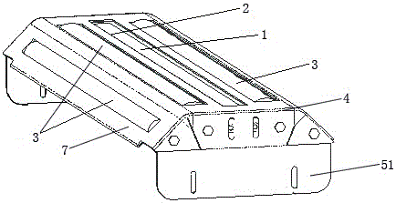
[0033] refer to Figure 1 to Figure 2 , the automatic counting device includes an infrared optical eye array 1, a protective plate 2, a roller 3, a control panel, and a mounting bracket 4.

[0034] Further, the infrared optical eye array 1 is a continuous reflective infrared optical eye array, the infrared optical eye array 1 is composed of infrared emitting devices and receiving devices, and the infrared optical eye array 1 is roughly in the shape of a cuboid. Composed of infrared emitting devices and receiving devices, the diodes are arranged in a row with a certain gap.

[0035] Further, the control panel has a piece counting module, a wireless transmission module, a speed control module, and an information processing module, and the piece counting module, the wireless transmission module, the speed control module, and the information processing module are electrically connected, and the control panel is built in in the automatic counting device.

[0036] Further, there a...

Embodiment 2

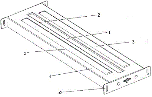
[0051] refer to Figure 3 to Figure 4 , including an infrared optical eye array 1, a protective plate 2, a roller 3, a control panel, a mounting bracket 4, and a connecting bracket 52.

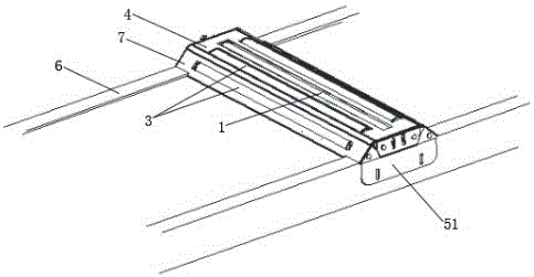
[0052] On the basis of Example 1, Figure 3 to Figure 4 When connecting two conveyors 6, the specific use state diagram of the automatic counting device of the technical solution, when connecting two conveyors 6, the connecting bracket 52 is image 3 or Figure 4 As shown, further, when two conveyors 6 are connected, the mounting bracket 5 does not have an inclined bracket 7, and the automatic counting device as a whole directly realizes seamless connection with the two conveyors 6, and its protective plate 2, roller 3 is consistent with the horizontal position of the conveyor belt of the conveyor 6.


PUM


Abstract

The invention provides a device for automatically counting express items on a conveyor. The device comprises an infrared light eye array, a protecting plate, at least two rollers, a control plate and mounting supports, wherein the infrared light eye array is a continuous reflecting type infrared light eye array and consists of an infrared transmitting device and an infrared receiving device; the rollers are fixedly mounted on two sides of the infrared light eye array and are parallel to the infrared light eye array; the protecting plate is mounted on the infrared light eye array; and the mounting supports are positioned on two sides of the rollers and two sides of the infrared light eye array, are perpendicular to the rollers and the infrared light eye array, and fix the rollers and the infrared light eye array.

Description

technical field [0001] The invention relates to the field of counting express pieces, in particular to an automatic counting device for express pieces of a conveyor. Background technique [0002] With the rapid development of express delivery and e-commerce, a large number of express shipments are generally transported by conveyors in the warehouse, and can only enter the delivery and distribution link after sorting. With the application of sorting information equipment, operators need to know the number of express items entering the sorting line in real time. These data are very beneficial to the evaluation and adjustment of operation efficiency. Therefore, the express counting efficiency is very important for the operator to improve sorting efficiency, reduce costs, and enhance competitiveness. [0003] At present, the traditional express counting is mainly realized by manual counting, barcode automatic equipment, and visual automatic equipment. Manual counting is to us...

Claims


Application Information

Patent Timeline
IPC IPC(8): B65G43/08
CPCB65G43/08B65G2203/0241B65G2203/044
Inventor 陈瑞
Owner SHENZHEN SEAGEN TECH
Learn More