Eureka AIR delivers breakthrough ideas for toughest innovation challenges, trusted by R&D personnel around the world.

Wire binding machine

A technology of binding machine and winding mechanism, which is applied to the parts of binding machines, binding materials, packaging, etc., and can solve problems such as low efficiency, high cost, and wire winding

Active Publication Date: 2016-07-20
ANHUI FUYUEDA ELECTRONICS CO LTD
View PDF5 Cites 2 Cited by
  • Summary
  • Abstract
  • Description
  • Claims
  • Application Information

AI Technical Summary

Problems solved by technology

[0002] At present, many short-distance wires are sold in the market, such as USB cables, audio cables, and motherboard plug-in cables. However, these wires need to be bundled with wire ropes and cable ties during transportation. It can prevent the wires from being entangled together. At present, it is mainly bundled manually. This method of bundling is not only inefficient, but also high in cost. Therefore, a wire binding machine that can quickly bundle wires is urgently needed in the market.

Method used


Image

  • Wire binding machine
  • Wire binding machine

Examples


Embodiment Construction

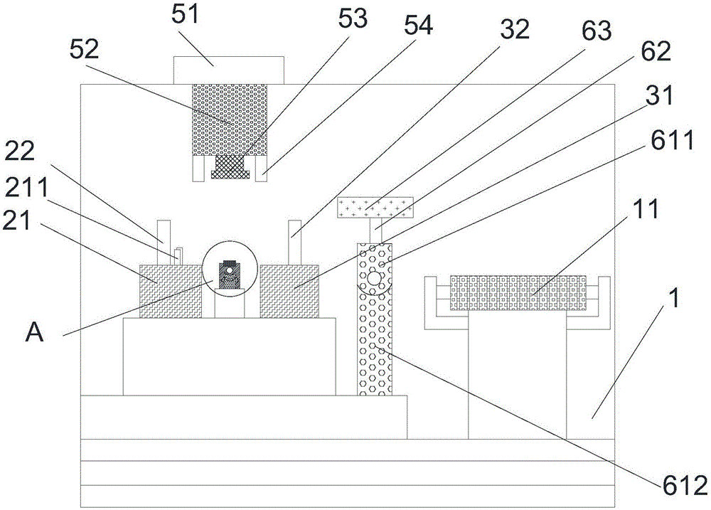
[0018] refer to figure 1 and figure 2 As shown, a kind of binding machine proposed by the present invention includes a frame 1, a first winding mechanism, a second winding mechanism, a binding rope cutting mechanism, a wire taking mechanism and a winding mechanism;

[0019] The first winding mechanism includes a first base 21 and a first support column 22, the first base 21 is installed on the frame 1, and the first support column 22 is vertically installed above the first base 21;

[0020] The second winding mechanism includes a second base 31 and a second support column 32, the second base 31 is installed on the frame 1, the second support column 32 is vertically installed above the second base 31, the second base 31 and the first The upper end of the base 21 is at the same height;

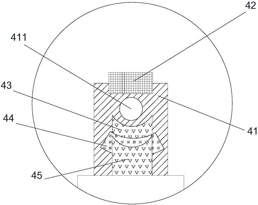
[0021] The wire binding rope cutting mechanism comprises a wire post 41, a cutting knife 42, a first wiring frame 43, a second wiring frame 44 and a third wiring frame 45, and the wire post 4...


PUM


Abstract

The invention provides a wire binding machine which comprises a rack, a first wire winding mechanism, a second wire winding mechanism, a wire binding rope cutoff mechanism, a wire taking mechanism and a wire coiling mechanism. The first wire winding mechanism comprises a first base and a first supporting column, the first base is mounted on the rack, and the first supporting column is vertically mounted above the first base. The second wire winding mechanism comprises a second base and a second supporting column, the second base is mounted on the rack, the second supporting column is vertically mounted above the second base, and the upper end of the second base and the upper end of the first base are located at the same height. The wire binding rope cutoff mechanism comprises a wire column, a cutter, a first connecting rack, a second connecting rack and a third connecting rack, and a wire through hole is formed in the wire column. The wire taking mechanism comprises a first movable frame, a second movable frame, a first clamping device and two abutting columns. The wire coiling mechanism comprises a mounting column, a rotating seat and a second clamping device. The wire binding machine is convenient to use, and the efficiency of wire binding can be effectively improved.

Description

technical field [0001] The invention relates to the wire packaging field, and specifically relates to a wire binding machine. Background technique [0002] At present, many short-distance wires are sold in the market, such as USB cables, audio cables, and motherboard plug-in cables. However, these wires need to be bundled with wire ropes and cable ties during transportation. It can prevent the wires from being entangled together. At present, the binding is mainly done manually. This binding method is not only inefficient, but also has high cost. Therefore, a wire binding machine that can quickly bind the wires is urgently needed in the market. Contents of the invention [0003] Based on the technical problems existing in the background technology, the present invention proposes a wire binding machine. [0004] A wire binding machine proposed by the present invention includes a frame, a first wire winding mechanism, a second wire winding mechanism, a wire binding rope cutt...

Claims


Application Information

Patent Timeline
IPC IPC(8): B65B13/16B65B13/20B65B13/18B65B27/06
CPCB65B13/16B65B13/18B65B13/20B65B27/06
Inventor 杨张平张勇储刘生董红玲
Owner ANHUI FUYUEDA ELECTRONICS CO LTD
Why Eureka
Eureka Blog
Learn More