
Design method for installation and pointing of dual-field-of-view star sensors for sun-synchronous orbit satellites

A sun-synchronous orbit and star sensor technology, which is applied in the direction of aerospace vehicle guides, aircraft, transportation and packaging, etc., can solve the complex design method and cannot provide the maximum sunlight and earth-atmospheric light shading for the star sensor hood Angle and other issues

Active Publication Date: 2017-10-24
TSINGHUA UNIV
View PDF6 Cites 0 Cited by
  • Summary
  • Abstract
  • Description
  • Claims
  • Application Information

AI Technical Summary

Problems solved by technology

[0005] In terms of research on star sensor installation and pointing methods, many research institutions have proposed design methods for practical applications. Among them, in view of the satellite's various working conditions and attitude conditions, Aerospace Dongfanghong proposed a star sensor installation angle based on mission planning in 2010 The determination method can solve the installation and pointing problem of a given star sensor under agile maneuvering conditions, but this method determines the appropriate installation angle of the star sensor by continuously adjusting the installation angle of the star sensor and the working conditions, and the design method is very complicated. Cannot give the maximum sunlight and earth-atmospheric light shielding angle of the star sensor hood under different installation pointing conditions

Method used


Image

  • Design method for installation and pointing of dual-field-of-view star sensors for sun-synchronous orbit satellites
  • Design method for installation and pointing of dual-field-of-view star sensors for sun-synchronous orbit satellites
  • Design method for installation and pointing of dual-field-of-view star sensors for sun-synchronous orbit satellites

Examples


Embodiment Construction

[0038] Embodiments of the present invention are described in detail below, examples of which are shown in the drawings, wherein the same or similar reference numerals designate the same or similar elements or elements having the same or similar functions throughout. The embodiments described below by referring to the figures are exemplary only for explaining the present invention and should not be construed as limiting the present invention.

[0039] In describing the present invention, it should be understood that the terms "center", "longitudinal", "transverse", "upper", "lower", "front", "rear", "left", "right", " The orientations or positional relationships indicated by "vertical", "horizontal", "top", "bottom", "inner" and "outer" are based on the orientations or positional relationships shown in the drawings, and are only for the convenience of describing the present invention and Simplified descriptions, rather than indicating or implying that the device or element refe...


PUM


Abstract

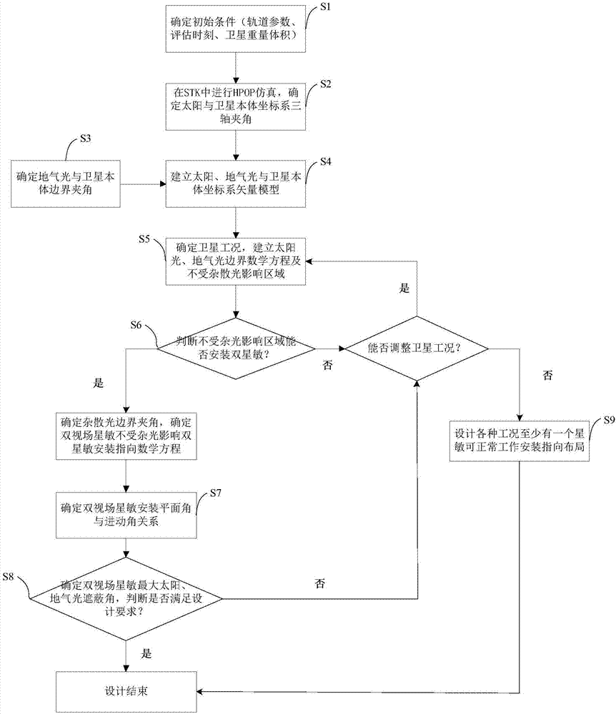
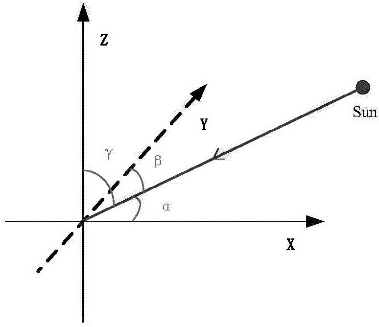
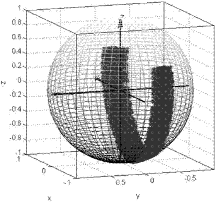
The invention discloses a dual-field star sensor mounting direction designing method for a satellite in sun-synchronous orbit. The method comprises the following steps: analyzing a vector relationship between stray light and a satellite body coordinate system based on a vector model between the stray light and the satellite body coordinate system in a satellite in-orbit operation period; calculating an area which is not influenced by the stray light by building a stray light boundary curve mathematic equation; calculating a star sensor direction equation through a boundary curve included angle relationship to obtain a relationship between a maximum sunlight shielding angle and a geogas light shielding angle designed for a star sensor shielding cover to restrain the stray light; and providing at least one star sensor work-ready scheme under a single working condition when mounting demands of two star sensors cannot be satisfied in an area free from the influence of the stray light. The method has the advantages that the problem that the mounting direction of the dual-field star sensor mounted on an aero-craft in sun-synchronous orbit is influenced by the stray light is solved effectively, and meanwhile, a theoretical basis is laid for design of a maximum sunlight shielding angle and a geogas light shielding angle for the dual-field star sensor shielding cover under different mounting conditions.

Description

technical field [0001] The invention relates to the field of spacecraft attitude measurement, in particular to a design method for installation and pointing of a sun-synchronous orbit satellite dual-view field star sensor. Background technique [0002] As a spacecraft attitude measurement device, star sensors use stars as attitude measurement references. Compared with other satellite attitude sensors (sun sensors, gyroscopes, magnetometers, etc.), they have high precision, no drift, low power consumption, and The advantage of outputting absolute attitude information is that it is currently the most widely used attitude sensor. During the operation of the satellite, the star sensor may be interfered by sunlight or atmospheric light, which will increase the background noise of the image plane of the star sensor, affect the accuracy of star point extraction, and even the star point will be submerged in the background stray light , causing the star sensor not to work properly. ...

Claims


Application Information

Patent Timeline
Patent Type & Authority Patents(China)
IPC IPC(8): B64G1/36
CPCB64G1/361
Inventor 邢飞王赓尤政
Owner TSINGHUA UNIV
Learn More