
Method for steering vehicle

A vehicle and sub-path technology, applied in general control systems, vehicle components, program control, etc., can solve problems such as limiting path global optimization and errors

Active Publication Date: 2016-07-13
ROBERT BOSCH GMBH
View PDF5 Cites 21 Cited by
  • Summary
  • Abstract
  • Description
  • Claims
  • Application Information

AI Technical Summary

Problems solved by technology

[0006] However, compared to manual parking in or out, this method can only be used in limited situations and often goes wrong in practice
Computational performance, which is usually only limited in vehicles, also severely limits the global optimization of the entire path

Method used


Image

  • Method for steering vehicle
  • Method for steering vehicle
  • Method for steering vehicle

Examples


Embodiment Construction

[0043] figure 1 A schematic diagram showing the vehicle kinematics model used. Vehicle 1 (not shown) has length l c and width w c , eg corresponds to the table shown, and moves in the direction of the vector v, where the vehicle initially has a vehicle orientation θ with respect to the coordinate system used. The two wheels on an axis are merged here to form an imaginary wheel 10 in each case in the center of the axis, the front wheels having a steering angle δ. In the described embodiment, the maximum steering angle is 45°. The distance between two wheels is the corresponding wheelbase L of the vehicle.

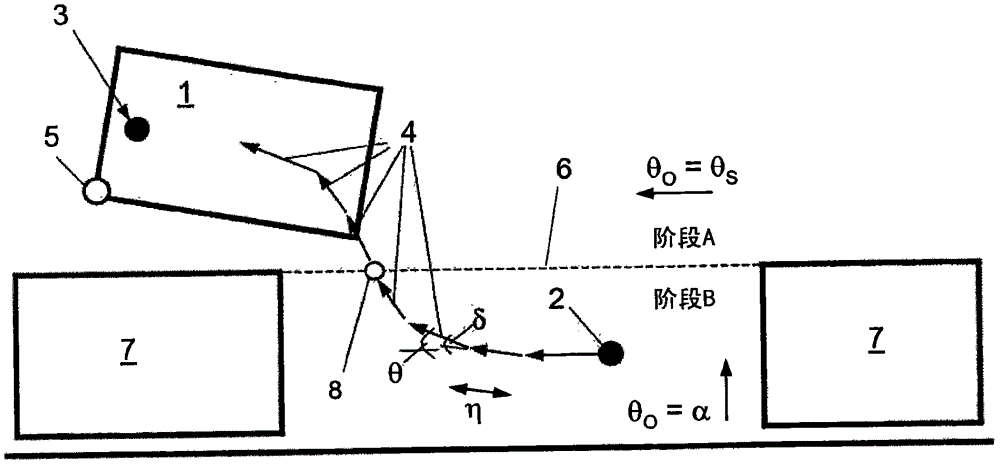
[0044] Figure 2a A vehicle 1 is shown which is located at a starting position 2 and is to be driven to an end position 3 without touching an obstacle 7 . For this purpose, a series of subpaths 4 is determined, wherein for each subpath a static optimization problem is solved.

[0045] Depending on the position of the corner points 5 of the vehicle relative to the imag...


PUM


Abstract

The invention relates to a method for steering a vehicle (1) around obstacles (7), from a starting position (2) to an end position (3). According to the method the vehicle is steered along a path, wherein the path comprises linear partial paths (4) defined by an increment [eta] and a steering angle [delta]. The method comprises the following steps: a) determining a maximum steering angle range and a maximum and a minimum increment range; b) determining the actual distance eP to the end position (3) and the target angle [theta]O, and the angle difference e[theta] between the current vehicle angle and the target angle; c) carrying out an optimization method for determining a partial path (4) by minimizing the value of a cost function lO assigned to the partial path, wherein (i) the cost function includes the current distance eP to the end position (3) and the current angle difference e[theta] to the target angle as optimization variables weighted independently of each other, and (ii) the maximum steering angle range, the maximum and the minimum increment range and a collision test are provided as boundary conditions; d) determining the new position by adding the detected partial path (4) to the current position; e) repeating the steps (b) to (d) until the end position (3) has been reached with sufficient accuracy.

Description

technical field [0001] The invention relates to a method for controlling a vehicle around an obstacle from a starting position to a final position, wherein the vehicle is controlled along a path. Background technique [0002] Methods for calculating a parking curve and a parking curve for a vehicle from a parking space or a garage are known from the prior art. Such a parking curve is used in an automatic parking system of the vehicle in order to assist the driver during parking in and out, or to carry out the parking process or the parking process fully automatically. [0003] Document DE 10 2012 211 721 A1 discloses a method for deriving a parking curve in which a vehicle is guided along a straight section and a single curved section with a constant radius of rotation in order to drive into a parking space. Said document also discloses a modified method in which the vehicle is guided along a first extending straight line, a second extending straight line and a third extend...

Claims


Application Information

Patent Timeline
Patent Type & Authority Applications(China)
IPC IPC(8): B62D15/02B25J9/16G05B19/4061G05D1/02G08G1/16
CPCB62D15/0285B62D15/027B62D15/025
Inventor M·伯克A·库吉P·齐普斯
Owner ROBERT BOSCH GMBH
Learn More