


Quick Research
Generate reliable direction feasibility study reports for your R&D in just a few steps.

Technical Q&A
Discover and master advanced knowledge NOW. Basics, ideas, possibilities, all at once.

Find Solutions
As an expert in R&D theories, this can generate solutions to your technical problems instantly.

Evaluate Feasibility
Analyze your overall solution with one click, know your potential R&D risks in advance.

Monitor Landscape
Get weekly tech updates, stay abreast of the latest tech innovations and key insights.
A Method of Dynamically Adjusting the Reflection Spectral Bandwidth of a Guided Mode Resonance Filter
A guided-mode resonance and filter technology, which is applied in the fields of optical communication and micro-electromechanical systems, can solve problems such as the size of a single spectral bandwidth and the dynamic adjustment of the spectral bandwidth of a guided-mode resonance filter.
- Summary
- Abstract
- Description
- Claims
- Application Information
AI Technical Summary
Problems solved by technology
Method used
Image


Examples
Embodiment 1
[0020] Example 1 Design of guided mode resonance filter with coupled grating structure
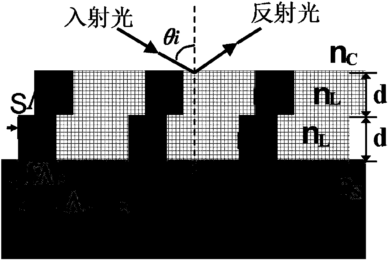
[0021] The guided mode resonant filter is designed with a coupled grating structure. The coupled grating is composed of two identical stacked sub-wavelength gratings with one-half the thickness of the dummy layer. For TM polarized incident light, at Brewster's angle In the vicinity, the electromagnetic field coupling between the upper and lower gratings is changed by controlling the micro / nano-level relative lateral movement of the two gratings, so as to realize the dynamic control of the bandwidth of the reflection spectrum of the guided mode resonance filter.
[0022] The design wavelength and material of the filter can be selected according to actual conditions. For TM polarization, select the design wavelength λ=650nm, and use HfO 2 And SiO 2 Two kinds of high and low refractive index materials, the refractive index is: n H = 1.98, n L = 1.46. The incident medium is air n c =1, the substra...
Embodiment 2
[0023] Embodiment 2 Based on the coupled grating structure to dynamically adjust the bandwidth of the guided mode resonance filter
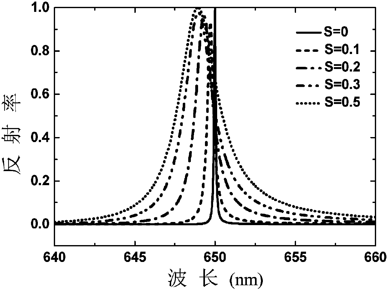
[0024] Based on the design of the guided-mode resonant filter using the coupled grating structure of Example 1, the vector diffraction theory is used to calculate the reflection filter spectrum curve of the guided-mode resonant coupled grating, and obtain figure 2 From the calculation results, it can be seen that due to the Brewster anti-reflection effect of TM polarization, the sideband reflectivity of the filter is less than 5‰ in the 200nm wavelength range near the design wavelength of 650nm, and the guided mode resonance reflection filtering performance superior.
[0025] in figure 2 Under the parameter conditions of, select different grating traverse coefficients S, for example, S is 0.1, 0.2, 0.3, 0.5, and use vector diffraction theory to calculate the reflection spectrum curve of the guided-mode resonance coupling grating, and get image 3 The...
Embodiment 3
[0026] Example 3 Fine-tuning the incident angle to compensate the peak wavelength shift phenomenon caused by the lateral shift of the grating
[0027] When the coupling grating based on Embodiment 2 is shifted laterally, the equivalent refractive index of the coupling grating will change slightly, resulting in a slight shift in the peak position of the filter with the change of S. In Example 2, the incident angle θ i =55.59°, when S=0, the coupling grating peak corresponds to the design wavelength of 650nm, but when S changes, the peak wavelength will slightly deviate from the design wavelength. For example, S is 0.1, 0.2, 0.3, 0.5, and the peak position is 649.7nm, 649.3nm, respectively , 648.9nm, 649.1nm. For the peak wavelength drift phenomenon caused when S changes, the peak wavelength drift can be compensated by fine-tuning the incident angle.
[0028] For example, for S=0.1, use vector diffraction theory to calculate the relationship between filter reflectivity and incident ...
PUM
 Abstract
Description
Claims
Application Information
 - R&D Engineer
- R&D Manager
- IP Professional
- Industry Leading Data Capabilities
- Powerful AI technology
- Patent DNA Extraction
Browse by: Latest US Patents, China's latest patents, Technical Efficacy Thesaurus, Application Domain, Technology Topic, Popular Technical Reports.
© 2024 PatSnap. All rights reserved.Legal|Privacy policy|Modern Slavery Act Transparency Statement|Sitemap|About US| Contact US: help@patsnap.com