Speed reducer
A technology of reducer and planetary gear, which is applied in the direction of mechanical equipment, gear transmission, belt/chain/gear, etc., can solve the problems of low input speed, difficulty in large torque transmission, difficulty in large reduction ratio, etc., and achieve low cost , high reliability, and simple manufacturing process
- Summary
- Abstract
- Description
- Claims
- Application Information
AI Technical Summary
Problems solved by technology
Method used
Image

Examples
Embodiment 1
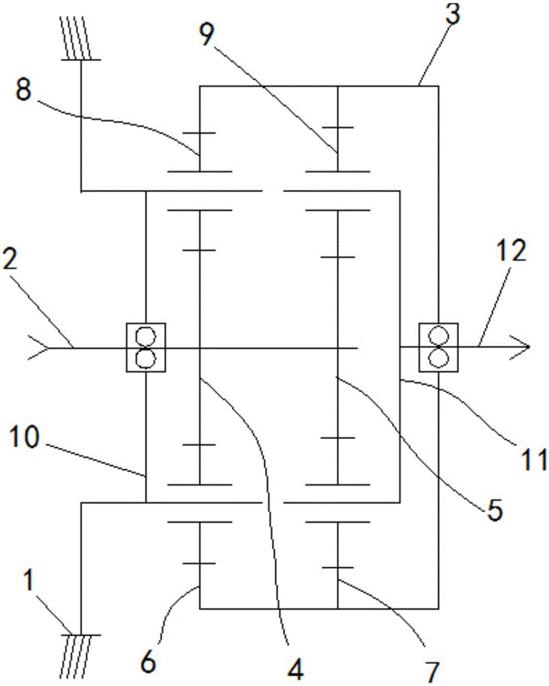
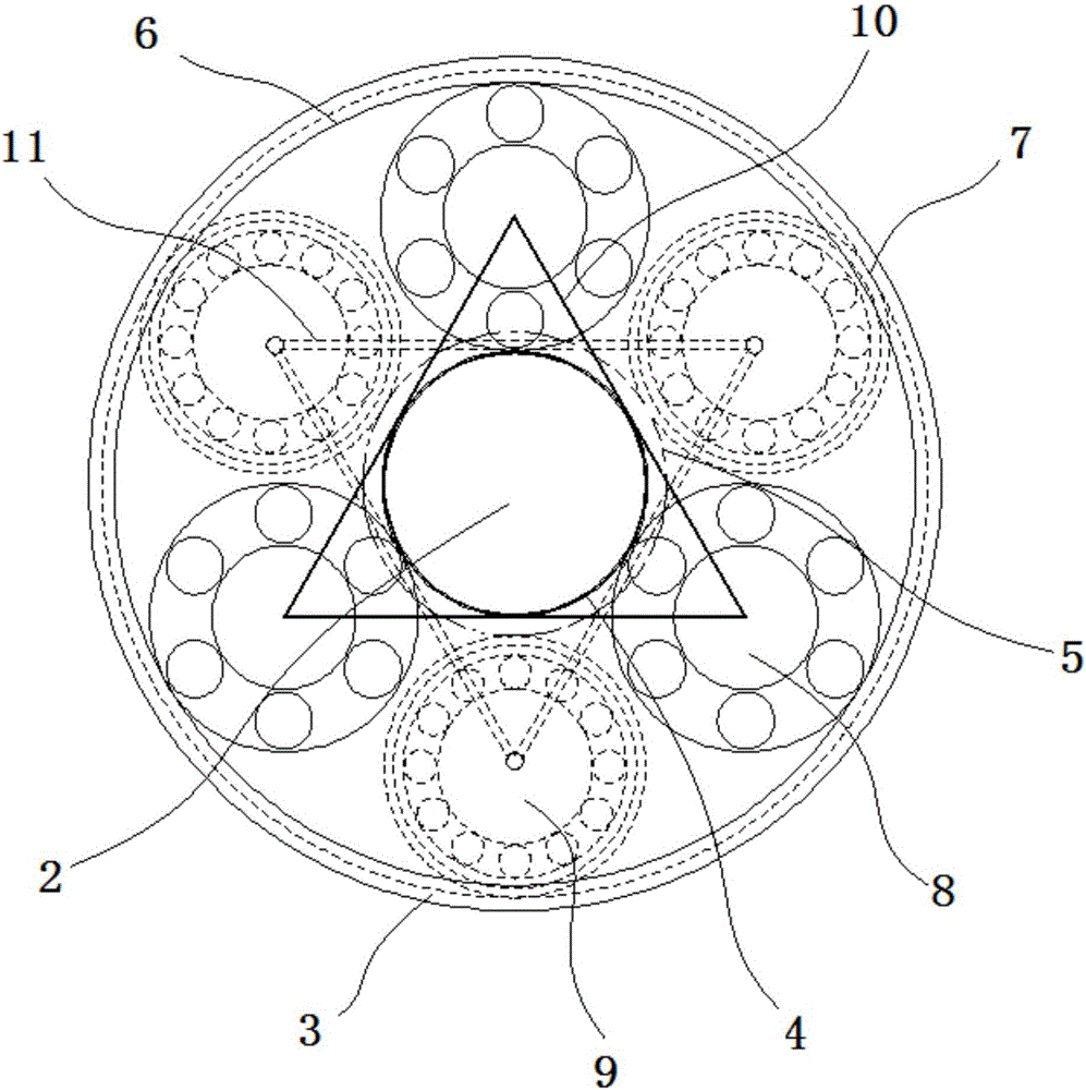
[0023] See figure 1 and figure 2 , a speed reducer, including a housing 1, an inner ring 2 arranged in the housing 1 and an outer ring 3 arranged on the periphery of the inner ring 2, and the outer wall of the inner ring 2 includes a first sun gear 4 and a second sun gear 5, the inner wall of the outer ring 3 contains a first ring gear 6 and a second ring gear 7, a set of first planetary gears 8 are meshed between the first sun gear 4 and the first ring gear 6, and the second A set of second planetary gears 9 is meshedly connected between the sun gear 5 and the second ring gear 7, a set of first planetary gears 8 is positioned and connected inside the first ring gear 6 through the first planetary gear cage 10, and a set of The second planetary gear 9 is positioned and connected inside the second ring gear 7 through the second planetary gear cage 11, and the second planetary gear cage 11 is fixedly connected with a transmission shaft 12; wherein, the first planetary gear cage...
Embodiment 2
[0030] See image 3 , a speed reducer, including a housing 1, an inner ring 2 disposed in the housing 1 and an outer ring 3 disposed on the periphery of the inner ring 2, the outer wall of the inner ring 2 includes a first sun gear 4 and a second The sun gear 5 includes a first ring gear 6 and a second ring gear 7 on the inner wall of the outer ring 3, and a set of first planetary gears 8 are engaged and connected between the first sun gear 4 and the first ring gear 6, A set of second planetary gears 9 is meshedly connected between the second sun gear 5 and the second ring gear 7, and a set of first planetary gears 8 is positioned and connected inside the first ring gear 6 through the first planetary gear cage 10. A set of second planetary gears 9 is positioned and connected inside the second ring gear 7 through a second planetary gear cage 11, and the second planetary gear cage 11 is fixedly connected with a transmission shaft 12; wherein, the first planetary gear cage 10 Wh...
Embodiment 3
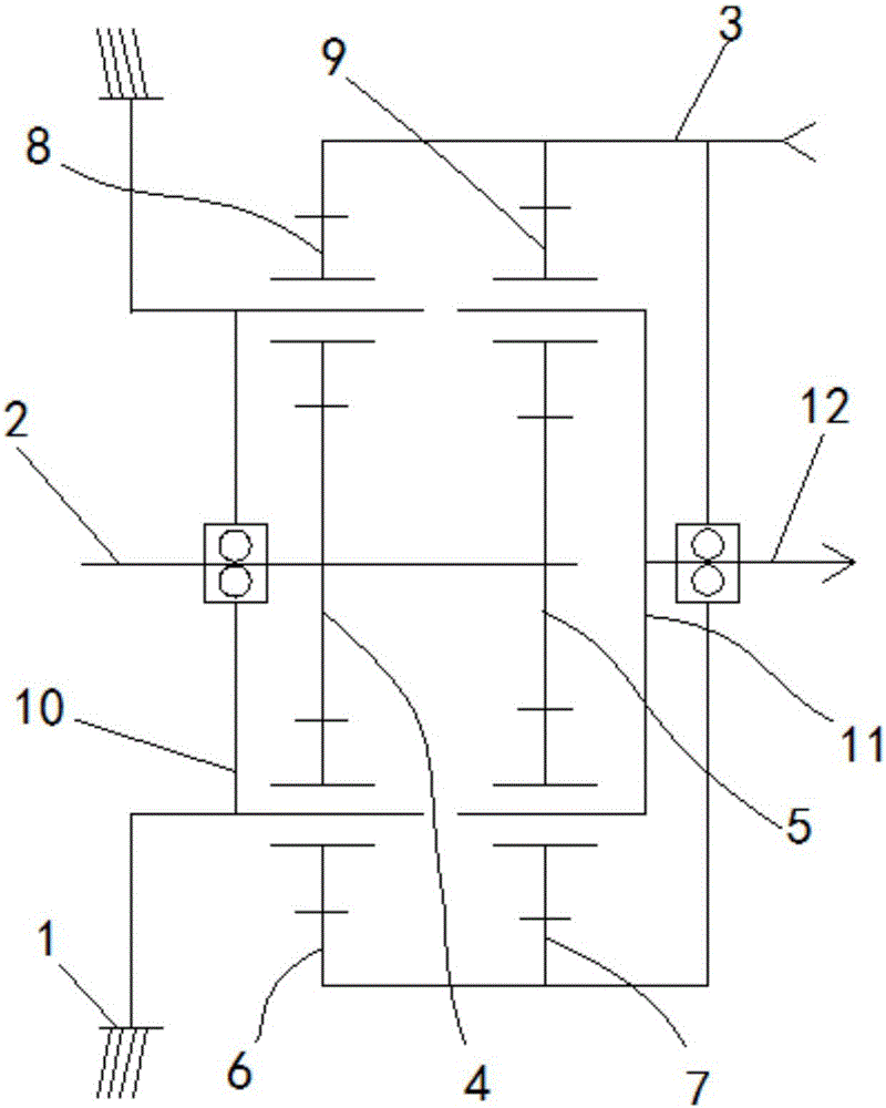
[0033] See Figure 4 , a speed reducer, including a housing 1, an inner ring 2 disposed in the housing 1 and an outer ring 3 disposed on the periphery of the inner ring 2, the outer wall of the inner ring 2 includes a first sun gear 4 and a second The sun gear 5 includes a first ring gear 6 and a second ring gear 7 on the inner wall of the outer ring 3, and a set of first planetary gears 8 are engaged and connected between the first sun gear 4 and the first ring gear 6, A set of second planetary gears 9 is meshedly connected between the second sun gear 5 and the second ring gear 7, and a set of first planetary gears 8 is positioned and connected inside the first ring gear 6 through the first planetary gear cage 10. A set of second planetary gears 9 is positioned and connected inside the second ring gear 7 through a second planetary gear cage 11, and the second planetary gear cage 11 is fixedly connected to a transmission shaft 12; wherein, the outer ring 3 is fixedly connected...
PUM
 Abstract
Description
Claims
Application Information
 - R&D
- Intellectual Property
- Life Sciences
- Materials
- Tech Scout
- Unparalleled Data Quality
- Higher Quality Content
- 60% Fewer Hallucinations
Browse by: Latest US Patents, China's latest patents, Technical Efficacy Thesaurus, Application Domain, Technology Topic, Popular Technical Reports.
© 2025 PatSnap. All rights reserved.Legal|Privacy policy|Modern Slavery Act Transparency Statement|Sitemap|About US| Contact US: help@patsnap.com