
Floor nozzle for a vacuum cleaner

A technology for vacuum cleaners, floors, applied in the direction of vacuum cleaners, suction nozzles, applications, which can solve the problem of not always ensuring effective cleaning, increasing work

Active Publication Date: 2016-07-13
威赛有限公司
View PDF7 Cites 0 Cited by
  • Summary
  • Abstract
  • Description
  • Claims
  • Application Information

AI Technical Summary

Problems solved by technology

However, the described embodiment of the floor nozzle comprising two articulation axes for tilting movement and design-related additional components increases assembly-related work in production
The nozzle body is also prone to inadvertent tilting motion when cleaning fabric floor surfaces, especially plush carpet, so that effective cleaning is not always ensured when moving the floor nozzle backwards

Method used


Image

  • Floor nozzle for a vacuum cleaner
  • Floor nozzle for a vacuum cleaner
  • Floor nozzle for a vacuum cleaner

Examples


Embodiment Construction

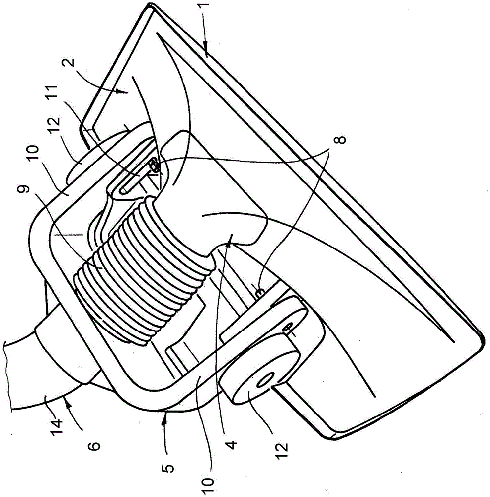
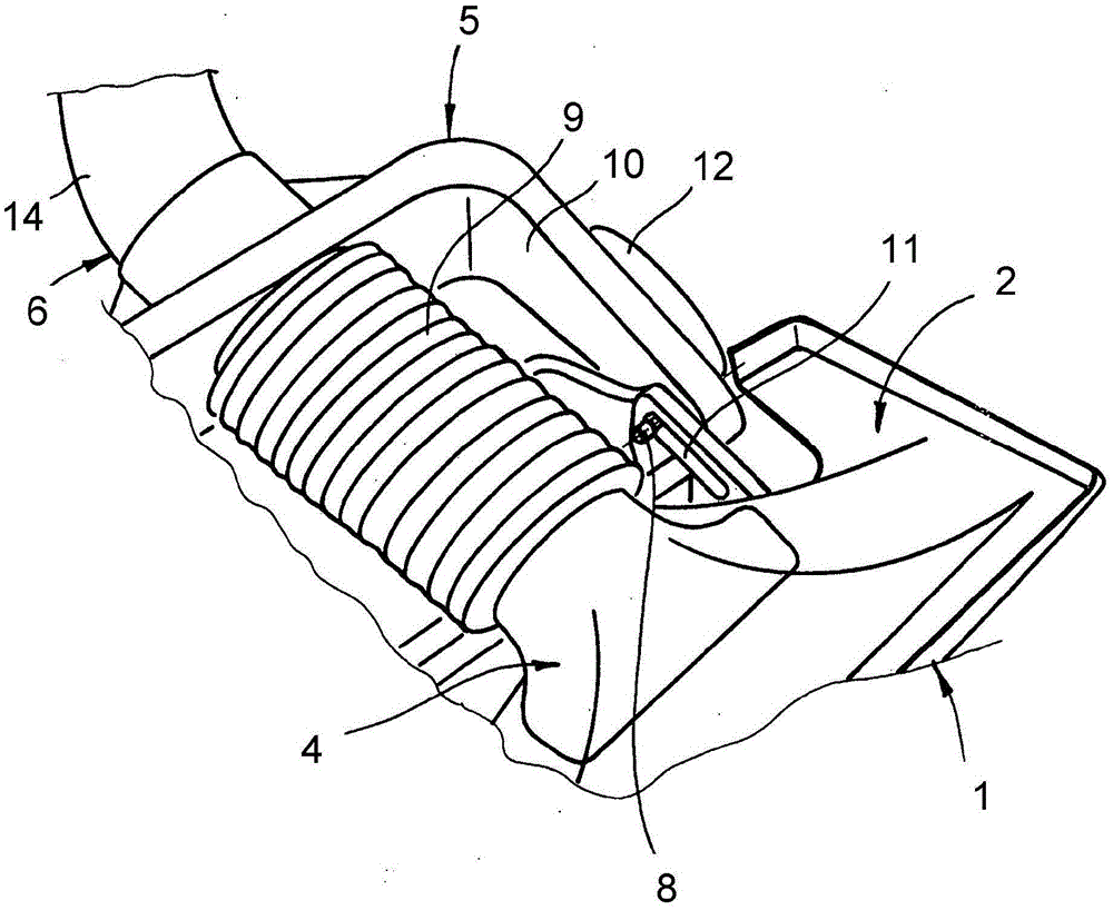
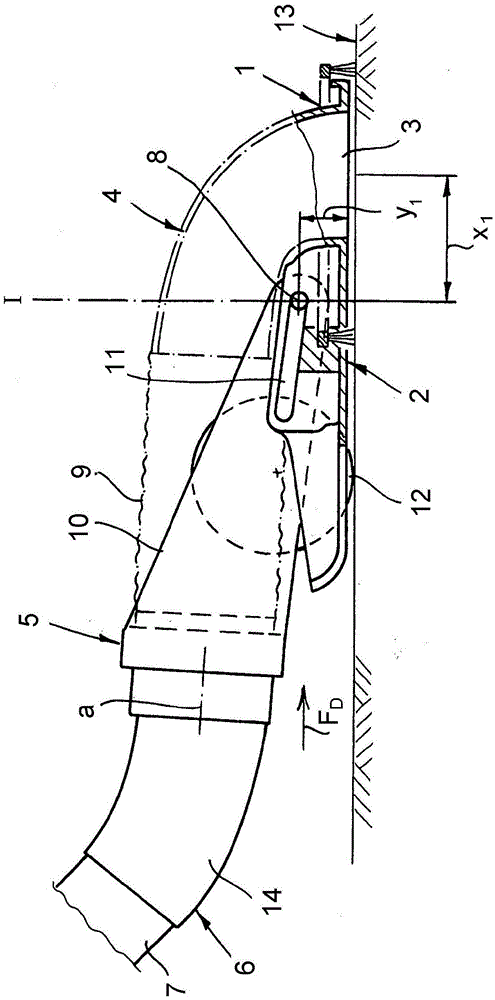
[0016] The figures show a so-called static floor nozzle for a vacuum cleaner that does not have any rotating cleaning tools. The floor nozzle comprises a nozzle body 1 with a bearing surface 2 at the bottom and a suction opening 3 and a suction channel 4 for discharging the flow of suction air flowing into the suction opening. Typically, the nozzle body 1 is also provided with a cover, but said cover is not essential to the function of the nozzle body and is therefore not shown in the drawings. The floor nozzle also comprises a support 5 having a connecting element 6 for the suction pipe 7 and connected to the nozzle body 1 so as to be pivotably movable about a pivot 8 . Provided between the suction tube connecting element 6 and the suction channel 4 are means for the fluid connection which compensate for the relative movement between the suction tube connecting element 6 and the suction channel 4 and for example Implemented as corrugated hose.

[0017] Compressive and tensi...


PUM


Abstract

A floor nozzle for a vacuum cleaner comprises: a nozzle body which is provided with a bearing surface at the bottom thereof and comprises a suction pipe and a suction channel used for discharging suction air flowing into a suction opening; and a support element which comprises a connecting element used for the suction pipe and is connected to the nozzle body so as to move pivotably around a pivot. A component used for fluid connection is arranged between the connecting element and the suction channel. When the floor nozzle moves to pass the floor surface in the form of forward movement and backward movement through the suction pipe connected to the connecting element, compressing force and tension force alternately act on the connecting element. According to the invention, the pivot can move between two operation positions which are spaced along the horizontal direction, wherein, the distance from the pivot to the suction opening when the pivot is in the first operation position is less than the distance from the pivot to the suction opening when the pivot is in the second operation position, the first operation position is result of the compressing force acting on the connecting element, and the second operation position is result of the tension force acting on the connecting element.

Description

technical field [0001] The present invention relates to a floor nozzle for a vacuum cleaner, the floor nozzle comprising a nozzle body having a bearing surface on the bottom and comprising a suction opening and a drain for discharging into the suction opening a suction channel for suction air flow; the floor nozzle comprises a support having a connecting element for the suction pipe and connected to the nozzle body so as to be pivotably movable about a pivot and all The floor nozzle includes a fluid connection between the connection element and the suction channel. Background technique [0002] A floor nozzle comprising said device is known, for example, from DE 10 2009 029 806 A1. The support has two housing parts, which are connected about a joint axis, wherein the nozzle body is pivotably supported on the front housing part of the nozzle body and serves for pumping. The connecting element of the drinking straw is arranged on the rear housing part. The supports are supp...

Claims


Application Information

Patent Timeline
IPC IPC(8): A47L9/02
CPCA47L9/0666A47L9/02
Inventor M·齐德克
Owner 威赛有限公司
Learn More