
Band-pass filter, high-order band-pass filter and performance analysis method

A technology of band-pass filter and analysis method, which is applied in the direction of waveguide devices, electrical components, circuits, etc., and can solve the problems of complex structure of band-pass filter and inability to take into account good selectivity

Inactive Publication Date: 2016-07-06
QINGDAO HAIER ELECTRONICS +1
View PDF2 Cites 18 Cited by
  • Summary
  • Abstract
  • Description
  • Claims
  • Application Information

AI Technical Summary

Problems solved by technology

[0004] One of the purposes of the present invention is to provide a band-pass filter to solve the problem that the structure of the band-pass filter in the prior art is complex and cannot take into account the characteristics of good selectivity and high-frequency out-of-band suppression

Method used


Image

  • Band-pass filter, high-order band-pass filter and performance analysis method
  • Band-pass filter, high-order band-pass filter and performance analysis method
  • Band-pass filter, high-order band-pass filter and performance analysis method

Examples


Embodiment Construction

[0025] In the following detailed description, a large number of specific details are proposed in order to provide a thorough understanding of the present invention. However, those skilled in the art will understand that the present invention can be implemented even without these specific details. In other cases, well-known methods, procedures, components and circuits are not described in detail so as not to affect the understanding of the present invention.

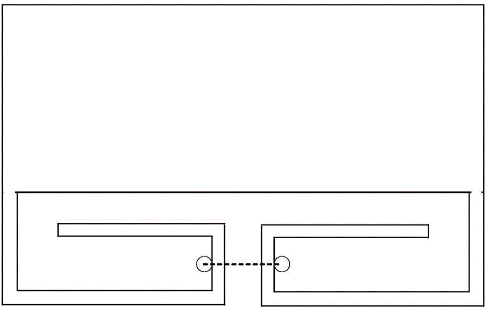
[0026] figure 1 The structure of the folded slot line resonator is shown. The structure of the coplanar stepped impedance resonator is destroyed by opening a via hole and connected by a microstrip connection line, while the original folded slot line structure remains unchanged.

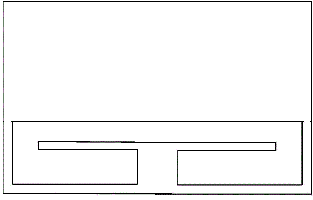
[0027] figure 2 The structure of the coplanar stepped impedance resonator is shown, and the bottom of the slot line is connected to destroy the folded slot line structure, while the original coplanar stepped impedance resonator structure remains unch...


PUM


Abstract

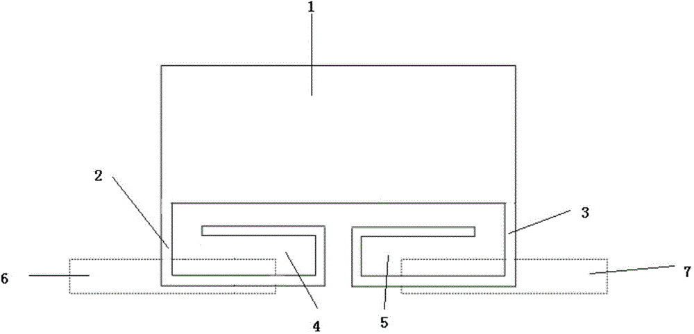
The invention relates to a band-pass filter. The band-pass filter comprises a resonator as well as an input feeder line and output feeder line which are arranged on the resonator; a first folded slot line, a connecting slot line and a second folded slot line of the resonator form a first resonant structure; and a first folded portion and a second folded portion of the resonator form a second resonant structure. The resonator provided with a coplaner stepped impedence resonator structure and a folded slot line resonator structure is designed, and therefore, the filter has the advantages of simple and compact structure, excellent selectivity, strong high-frequency out-of-band rejection and the like. Two or three such band-pass filters can be connected in cascade, so that a fourth-order band-pass filter and a sixth-order band-pass filter having excellent selectivity and strong high-frequency out-of-band rejection can be designed easily.

Description

[0001] This application claims the priority of the application number 201410714066.7, the application date November 28, 2014, and the title of the invention "a band pass filter and high-order band pass filter and performance analysis method" Technical field [0002] The invention relates to the technical field of passive filters, in particular to a band-pass filter, a high-order band-pass filter and a performance analysis method. Background technique [0003] In modern microwave communication systems, bandpass filters (BPF) need to have good performance, such as miniaturization, good selectivity, high out-of-band suppression, and strong out-of-band suppression capabilities. However, traditional multimode bandpass filters often use stub back-stacked resonators to achieve better selectivity, but they have more stray passbands. In recent years, Defective Ground (DGS) resonators have shown many advantages in filter design. The designer has designed a wideband filter with better high ...

Claims


Application Information

Patent Timeline
IPC IPC(8): H01P1/203
Inventor 彭彪李书芳翟翌立刘超王帅周源
Owner QINGDAO HAIER ELECTRONICS
Learn More