
Fresh air pretreatment geothermal exchange system

An exchange system and pretreatment technology, applied in geothermal energy, air conditioning system, geothermal energy power generation and other directions, can solve the problems of small amount of condensed water, dust accumulation, inability to collect, etc., achieve low temperature impact resistance, reduce indoor pollution sources, and resist Good chemical corrosion effect

Active Publication Date: 2019-04-12
山东省建筑工程质量检验检测中心有限公司 +1
View PDF8 Cites 0 Cited by
  • Summary
  • Abstract
  • Description
  • Claims
  • Application Information

AI Technical Summary

Problems solved by technology

Due to the serious outdoor air pollution in China, if the outdoor fresh air directly enters the buried ventilation duct without treatment, it will inevitably cause dust collection and microbial growth in the buried ventilation duct.
In this way, the fresh air processed through the buried pipe will become a new source of pollution, and entering the room will deteriorate the indoor air quality
[0004] 2. The original patent lacks detailed calculation methods for the setting of technical indicators such as buried ventilation pipe material, buried depth, pipe length, slope, and wind speed
In actual engineering, since the amount of condensed water is closely related to the outdoor meteorological conditions, the amount of air supply and the cooling effect of the geothermal heat exchanger, there is a possibility that the amount of condensed water is relatively small, cannot be collected, attached to the pipe wall, and cannot be discharged. Problems with dust accumulation and mold growth
The original patent did not consider taking corresponding technical measures to solve this problem
[0006] 4. The original patent lacks the monitoring function of the actual operation effect of the geothermal exchange system
There is a lack of monitoring of the effect of fresh air pretreatment, and it is impossible to judge whether the system operation has achieved the expected effect

Method used


Image

  • Fresh air pretreatment geothermal exchange system
  • Fresh air pretreatment geothermal exchange system
  • Fresh air pretreatment geothermal exchange system

Examples


Embodiment Construction

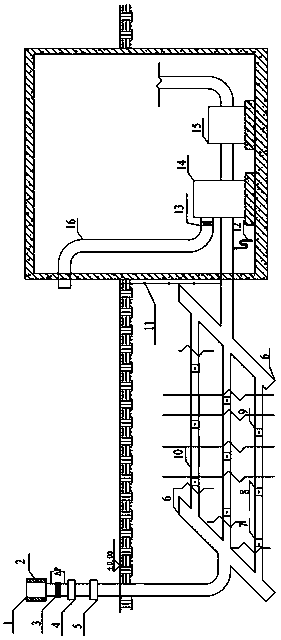
[0029] Such as figure 1 Shown: a ground heat exchange system for fresh air pretreatment, which includes three parts: an outdoor fresh air intake part, a geothermal exchange part, and an indoor fresh air processing part connected through a ventilation pipeline. The outdoor fresh air intake part is set on the ground, and the outdoor fresh air intake The part includes the fresh air outlet 1 arranged and connected in order from top to bottom, the medium-efficiency filter device 3, the electrostatic precipitator 4, and the solid dehumidification device 5; 2. For particle size ≥ 5.0μm, filtration efficiency 90 > E ≥ 70%,; medium-efficiency filter device 3, the initial resistance of medium-efficiency filter is about 50-90Pa, the final resistance is about 100-180Pa, for particle size ≥ 1.0μm, filtration efficiency 99>E≥70%. The solid dehumidification device is a cylindrical solid adsorption dehumidification fixed bed, and a grid plate or an orifice plate for placing a solid adsorbent...


PUM


Abstract

The invention relates to a fresh air pretreatment terrestrial heat exchange system. The fresh air pretreatment terrestrial heat exchange system comprises an outdoor fresh air taking part, a terrestrial heat exchange part and an indoor fresh air treatment part, wherein the outdoor fresh air taking part, the terrestrial heat exchange part and the indoor fresh air treatment part are communicated through ventilation pipelines. The fresh air pretreatment terrestrial heat exchange system is characterized in that the outdoor fresh air taking part is arranged on the ground, the outdoor fresh air taking part comprises a fresh air port, a coarse-efficiency filter device, a medium-efficiency filter device, an electrostatic dust collector and a solid dehumidification device which are arranged in sequence from top to bottom and are communicated; the terrestrial heat exchange part comprises buried pipes, temperature measuring points which are formed on the buried pipes, pneumatic cleaning device reserved openings and flow measuring points; the indoor fresh air treatment part comprises a fresh air unit, a drain pipe, a fresh air valve, a plenum chamber and a fresh air pipeline.

Description

technical field [0001] The invention relates to a geothermal exchange system, in particular to a fresh air pretreatment geothermal exchange system. Background technique [0002] In the prior art, there is a buried pipe energy-saving ventilation system, and its unresolved problems mainly include: [0003] 1. In the original patent, the outdoor fresh air first enters the room through the buried pipe, and a filter device is installed at the entrance of the indoor fresh air unit, while no filter and dust collection device is installed at the outdoor fresh air inlet. Due to the serious outdoor air pollution in China, if the outdoor fresh air directly enters the buried ventilation duct without treatment, it will inevitably cause dust collection and microbial growth in the buried ventilation duct. In this way, the fresh air processed through the buried pipe will become a new source of pollution, and entering the room will deteriorate the indoor air quality. [0004] 2. The origin...

Claims


Application Information

Patent Timeline
Patent Type & Authority Patents(China)
IPC IPC(8): F24F5/00F24F13/28F24T10/13
CPCF24F5/0046F24F13/28F24T10/10Y02B10/40Y02E10/10
Inventor 王昭李震李迪李向前宋文寅孙璐楠时敬磊
Owner 山东省建筑工程质量检验检测中心有限公司
Learn More