
Driving technique for inner motor of switched reluctance drive (SRD) hub

An internal drive and wheel hub technology, applied in electric components, synchronous motors connected with control/drive circuits, used for single-phase current, etc., can solve problems such as complex structure, unsprung mass and large moment of inertia

Inactive Publication Date: 2016-07-06
韦翔
View PDF4 Cites 1 Cited by
  • Summary
  • Abstract
  • Description
  • Claims
  • Application Information

AI Technical Summary

Problems solved by technology

[0019] In order to overcome the shortcomings of the existing hub motor technology, such as complex structure, unsprung mass and large moment of inertia, etc.

Method used


Image

  • Driving technique for inner motor of switched reluctance drive (SRD) hub
  • Driving technique for inner motor of switched reluctance drive (SRD) hub

Examples


Embodiment

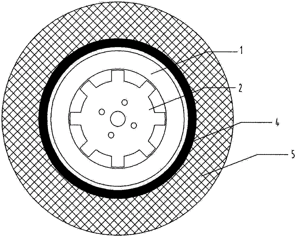
[0028] Example: such as figure 1 As shown, taking the structure of a 12 / 8 switched reluctance motor as an example, the driving part of the SRD drive device is composed of a stator 1 and a rotor 2. The stator 1 and the rotor 2 are made of silicon steel sheets with excitation functions and other materials. A coil 3 is provided. When the external speed controller controls the current on and off of the six pairs of salient pole coils 3 on the stator 1 according to the positions of the stator 1 and the rotor 2, the rotor 2 will rotate; Control, switch this driving device to the effect of slowing down the car (power generation state) or braking (reverse rotation). Such as figure 2 As shown, the driving device in the SRD hub is composed of a stator 1, a rotor 2, a hub 4 connected to the rotor and a tire 5. The stator 1 is fixed on the suspension of the locomotive and is located on the outer peripheral side or both sides of the rotor 2 . The rotor 2 is connected with the locomoti...


PUM


Abstract

The invention relates to a locomotive drive technology driven by an in-wheel motor using switched reluctance motor (SRD) technology. Usually, this SRD in-wheel motor drive technology is applied in the wheel hub of gasoline-electric hybrid locomotives and pure electric locomotives. The invention can drive and actively brake the locomotive by setting an SRD (switched reluctance motor) drive in the wheel hub without changing the existing wheel hub of the locomotive, and can recover the braking energy. Compared with the current mainstream new energy vehicles, the motors are connected in parallel or in series at the engine side of the vehicle, without major changes to the vehicle itself, and can be applied to most locomotives. The cost of development and transformation is low, and the structure is simple. Since the active control ensures that the engine of the locomotive works under better working conditions most of the time, the fuel economy of the locomotive is improved.

Description

technical field [0001] The invention relates to a driving technology of a new energy vehicle driven by a motor in a hub using a switched reluctance motor (SRD) technology. Usually, this SRD in-wheel motor drive technology is applied in the wheel hub of gasoline-electric hybrid locomotives and pure electric locomotives. Background technique [0002] New energy vehicles have now become a forward-looking field in the automotive industry, and the driving technology of new energy vehicles is quite different from traditional internal combustion engine vehicles, and one type of driving technology has great development prospects, which is in-wheel motor technology. [0003] In-wheel motor technology, also known as in-wheel motor technology, is characterized by the integration of power, transmission and braking devices into the wheel hub, thus greatly simplifying the mechanical parts of electric vehicles. Wheel hub motor technology is not new. As early as 1900, Porsche first produce...

Claims


Application Information

Patent Timeline
IPC IPC(8): B60K7/00H02K19/10H02K1/14H02K11/30
CPCB60K7/0007H02K1/145H02K19/10
Inventor 韦翔
Owner 韦翔
Learn More