Power component locking and mounting device

A technology of power components and installation devices, which is applied in the field of locking installation devices, and can solve problems such as complex disassembly, complex unlocking, and complex operation

Inactive Publication Date: 2016-06-29
HANGZHOU QIAOER ARTS & CRAFTS CO LTD
View PDF4 Cites 1 Cited by
  • Summary
  • Abstract
  • Description
  • Claims
  • Application Information

AI Technical Summary

Problems solved by technology

However, some existing locking elements are complicated to operate, which is not conducive to the initial disassembly and assembly of power elements
And some devices with locking function are complex to unlock, although easy to install but complicated to disassemble
Therefore, these devices all bring difficulties to the quick disassembly and assembly of power and electrical components.

Method used


Image

  • Power component locking and mounting device
  • Power component locking and mounting device

Examples


Embodiment Construction

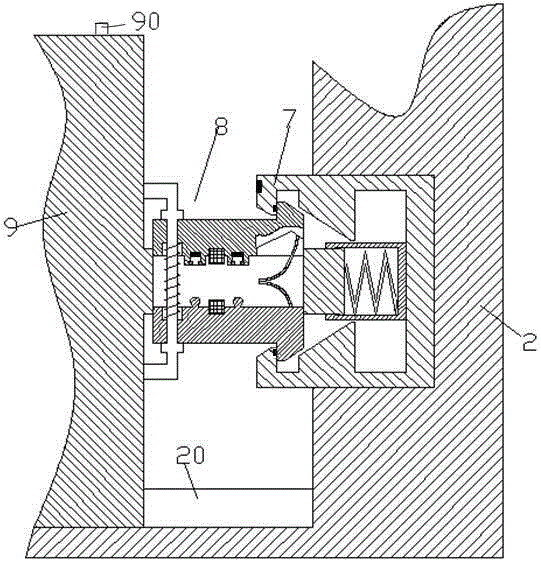
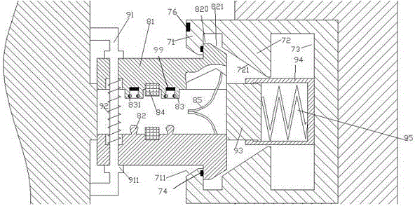
[0008] Combine below Figure 1-2 The present invention will be described in detail.

[0009] A locking installation device for electric components according to an embodiment of the present invention, comprising an electrical cabinet body 2 with a horizontal track 20 and an electric component 9 capable of sliding on the horizontal track 20, the electrical cabinet body 2 is fixedly provided with a locking and unlocking insert 7 on the vertical rear wall, wherein, the power element 9 is fixedly provided with a protrusion 93 for protruding into the inner cavity of the locking and unlocking insert 7, and the protrusion A sliding chamber is provided in the outlet portion 93 for slidingly installing two symmetrically arranged locking sliding wedges 81 , and the left ends of the two locking sliding wedges 81 are controlled by a guide rod 91 fixedly arranged on the power element 9 . Pass through and be limited by the limit protrusion 911 on the guide rod 91 so as to limit the two lock...


PUM


Abstract

A locking installation device for power components, comprising an electrical cabinet body (2) having a horizontal rail (20) and a power component (9) capable of sliding on the horizontal rail (20), the electrical cabinet A locking and unlocking insert (7) is fixedly arranged on the vertical rear wall of the body (2), wherein the power element (9) is fixedly arranged to protrude into the inner cavity of the locking and unlocking insert (7) The protruding part (93) of the protruding part (93) is provided with a sliding cavity for slidingly installing two symmetrically arranged locking sliding wedges (81).

Description

technical field [0001] The invention relates to the field of electric cabinets, in particular to a locking installation device for electric components. Background technique [0002] In the field of power electrical cabinets, in order to facilitate the installation and locking of power components, a chute can be provided to slide the power components in and lock them with another locking device. However, the operation of some existing locking elements is complicated, which is not conducive to the initial disassembly and assembly of the power elements. And some devices with locking function are complicated to unlock, although they are easy to install but complicated to disassemble. Therefore, these devices all bring difficulty to quickly disassembling and assembling electric power components. Contents of the invention [0003] The object of the present invention is to provide a locking installation device for electric components, which can overcome the above-mentioned defe...

Claims


Application Information

Patent Timeline
IPC IPC(8): H02B1/052
CPCH02B1/0523
Inventor 翟茵邯
Owner HANGZHOU QIAOER ARTS & CRAFTS CO LTD
Why Eureka
Try Eureka