Anti-theft locking device for power transformer
A technology of power transformers and locking devices, which is applied in the direction of circuit devices, transformer/reactor installation/support/suspension, electrical components, etc., can solve the problems of limited anti-theft effect and electronic monitoring anti-theft technology cannot be effectively prevented, and achieve structural simple effect
- Summary
- Abstract
- Description
- Claims
- Application Information
AI Technical Summary
Problems solved by technology
Method used
Image
Examples
specific Embodiment approach 1
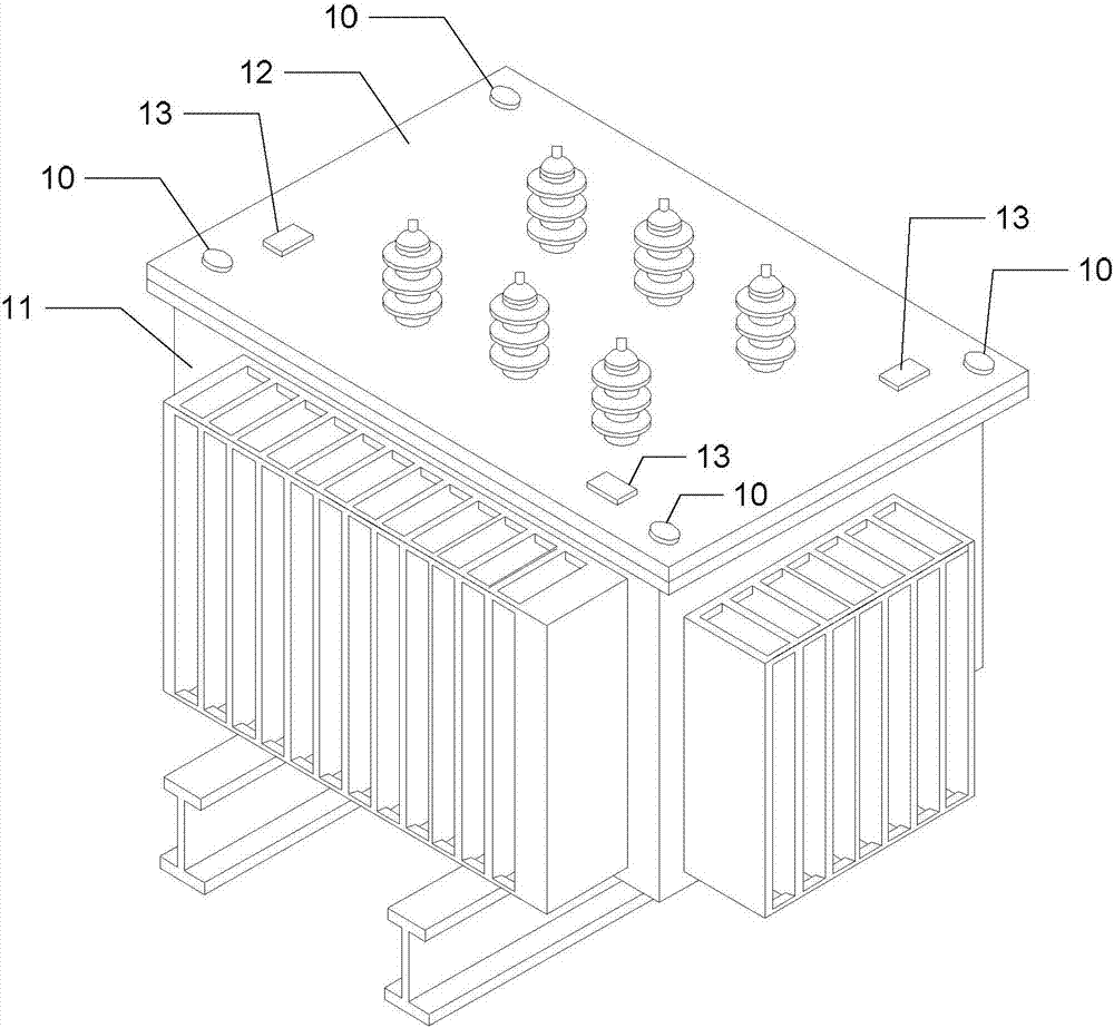
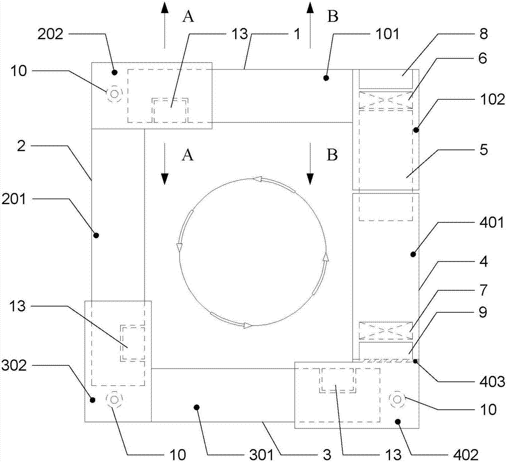
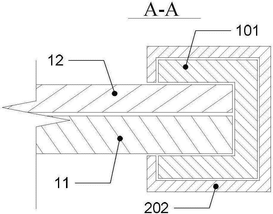
[0039] Specific implementation mode one: the following combination Figure 1 to Figure 17 Describe this embodiment, the anti-theft locking device of the power transformer described in this embodiment, the transformer casing 11 and the transformer upper cover 12 are connected by a bolt and nut structure 10; the transformer upper cover 12 is a rectangular plate structure, and the quadrilateral shape of the rectangular plate The three corners are provided with bolt and nut structures 10;
[0040] The anti-theft locking device includes No. 1 L-shaped locking plate 1, No. 2 L-shaped locking plate 2, No. 3 L-shaped locking plate 3, No. 4 L-shaped locking plate 4, locking bolt plate 5, No. 1 electromagnet 6, and No. 2 Electromagnet 7, No. 1 control unit 8, No. 2 control unit 9, three locking blocks 13, main control unit 14 and hand-held wireless remote control switch 15;
[0041] A locking block 13 is fixed near each bolt and nut structure 10 on the transformer upper cover 12;
[0...
specific Embodiment approach 2
[0066] Specific implementation mode two: the following combination Figure 16 and Figure 17 Describe this embodiment, this embodiment will further explain Embodiment 1, the main control unit 14 includes a main controller 14-1, a wireless energy transmission unit 14-2 and a main control wireless communication unit 14-3; the main controller 14-1 The alternating current provided by the transformer is used as the working power supply;
[0067] No. 1 control unit 8 includes No. 1 controller 8-1, No. 1 wireless energy receiving unit 8-2, No. 1 storage battery 8-3, No. 1 power detection unit 8-4 and No. 1 wireless communication unit 8-5; No. battery 8-3 provides operating power for No. 1 controller 8-1 and No. 1 electromagnet 6, and No. 1 controller 8-1 controls the switch of No. 1 electromagnet 6; No. 1 controller 8-1 passes through No. 1 power The detection unit 8-4 detects the power of the No. 1 storage battery 8-3. When the power is insufficient, the No. 1 controller 8-1 per...
PUM
 Abstract
Description
Claims
Application Information
 - R&D Engineer
- R&D Manager
- IP Professional
- Industry Leading Data Capabilities
- Powerful AI technology
- Patent DNA Extraction
Browse by: Latest US Patents, China's latest patents, Technical Efficacy Thesaurus, Application Domain, Technology Topic, Popular Technical Reports.
© 2024 PatSnap. All rights reserved.Legal|Privacy policy|Modern Slavery Act Transparency Statement|Sitemap|About US| Contact US: help@patsnap.com


