
Backup camera system for automatically switching tri-state view angle and backup camera device of backup camera system

A technology of automatic switching and photographing devices, applied in optical observation devices, vehicle parts, transportation and packaging, etc., can solve problems such as blind spots, inability for drivers, and inability to automatically switch between different perspectives

Inactive Publication Date: 2016-06-29
SEEWAYS TECH
View PDF5 Cites 7 Cited by
  • Summary
  • Abstract
  • Description
  • Claims
  • Application Information

AI Technical Summary

Problems solved by technology

Generally, the traditional sound wave radar for reversing mainly detects the sound wave signal reflected by the obstacle, and then sends out a warning sound; When the height is less than 30-45 cm, it will be impossible to detect, and its width is also limited to a fan-shaped area, so it has blind areas that cannot be detected in terms of return depth, detection height and width , and the reversing sound wave radar only informs the driver that there is an obstacle behind with a warning sound, but the driver cannot know the distance or position of the obstacle through the reversing sound wave radar, so the driver cannot use the reversing sound wave radar to Get the real situation behind the vehicle
[0004] Although a reversing camera was later developed to match the reversing sonic radar to reflect the real scene behind the vehicle. However, the horizontal viewing angle of the general reversing camera is at most 140 to 150 degrees, so it will exist due to its insufficient viewing angle. There are blind spots. In addition, because the general reversing camera cannot automatically switch between different viewing angles, when the vehicle is reversing and approaches a vertical object, it will not be able to switch to the overlooking angle, which may cause collisions or accidents.
For example, if the vehicle is reversing and the rear of the vehicle is close to vertical objects such as ravines, cliffs, or harbor embankments, it is difficult for the driver to determine the real situation behind the vehicle because it cannot switch to the overlooking angle in real time. It may cause the rear wheels of the vehicle to fall into the ravine or cliff, or collide with the harbor embankment and other dangers
[0005] In addition, the general reversing wide-angle camera, which has a wide-angle scene, a standard angle of view scene, and a bird’s-eye view scene, must be manually switched by the driver to produce the most suitable field of view for reversing. However, reversing is a continuous action. It is very inconvenient for the user to manually switch the screen after a pause
[0006] In view of this, how to develop a reversing camera system and its reversing camera device that automatically switches three-state viewing angles to solve the existing blind spots in the existing reversing sound wave radar and reversing special cameras, and the inability to automatically switch between different viewing angles, resulting in uncertainty when reversing. The problem of the real situation of the front and rear of the vehicle is actually a subject to be solved at present

Method used


Image

  • Backup camera system for automatically switching tri-state view angle and backup camera device of backup camera system
  • Backup camera system for automatically switching tri-state view angle and backup camera device of backup camera system
  • Backup camera system for automatically switching tri-state view angle and backup camera device of backup camera system

Examples


Embodiment Construction

[0037] Some typical embodiments embodying the features and advantages of the present invention will be described in detail in the description in the following paragraphs. It should be understood that the present invention can have various changes in different implementations without departing from the scope of the present invention, and that the description and drawings in the description are used as illustrations in nature and not for limiting the present invention. invention.

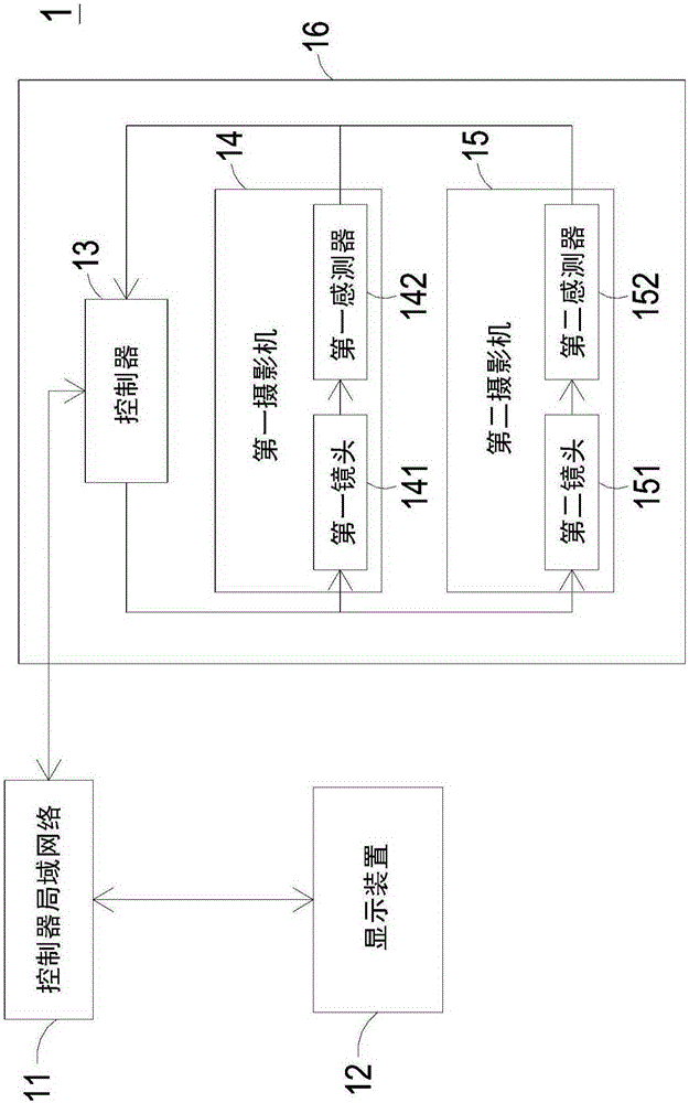
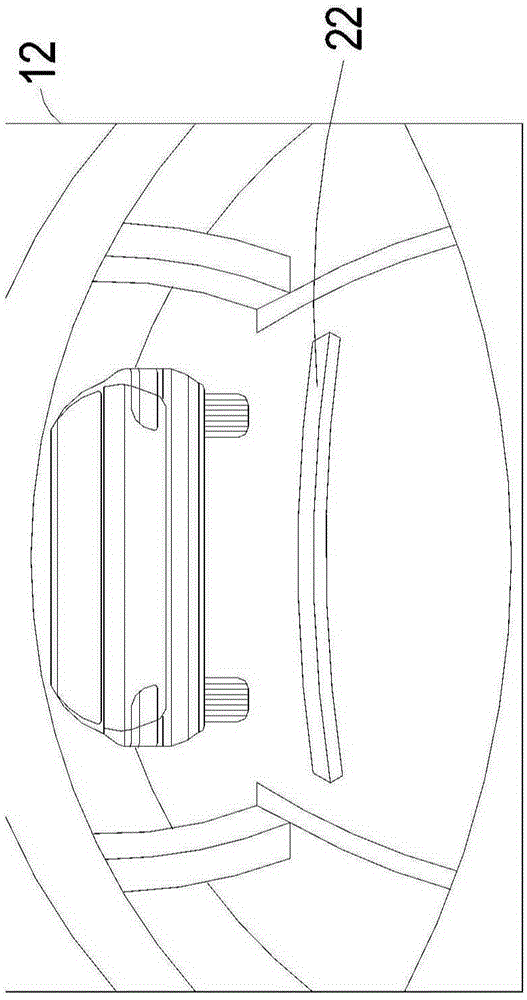
[0038] figure 1 It is a schematic structural diagram of a reversing camera system for automatically switching three-state viewing angles according to a preferred embodiment of the present invention. Such as figure 1 As shown, the reversing camera system of the present invention that automatically switches the three-state viewing angle is applicable to the vehicle 10 (such as figure 2 shown), and it includes a controller area network (CANBus) 11, a display device 12 and a reverse camera device 16, ...


PUM


Abstract

The invention discloses a backup camera system for automatically switching tri-state view angles and a backup camera device of the backup camera system. The backup camera system comprises a controller local network, a backup camera device, a first camera, a second camera and a display device, wherein the backup camera device comprises a controller; the first camera comprises a first lens and a first sensor; the second camera comprises a second lens and a second sensor; the controller of the backup camera device is used for capturing vehicle information parameters of the controller local network, used for judging the state of a vehicle as one of multiple scenes, and used for automatically switching the cameras to be powered on or powered off according to scene judgment; the first sensor and the second sensor can be used for judging a first distance or a second distance, used for automatically switching the lenses to be tri-state view angles of wide angle view, normal view or overlook view according to values of the first distance and the second distance, and used for displaying the tri-state view angles of the lenses on the display device. By adopting the backup camera system, a driver can switch to obtain a most appropriate tri-state view angle image according to different distances when backing up or packing a vehicle, and current situations in front of and behind the vehicle can be judged.

Description

technical field [0001] The present invention relates to a reversing camera device, in particular to a reversing camera system and a reversing camera device capable of automatically switching three-state viewing angles by using image detection. Background technique [0002] With the improvement of transmission system, material science and rapid economic growth, today's vehicles have become highly mobile and popularized, which greatly saves the time it takes to travel to the destination. With the increase in the number of vehicle users, driving safety has become one of the development priorities of today's vehicle technology. [0003] For a long time, in the technical development of vehicle driving safety, in addition to the driving vision between vehicles, the safety distance from the front and rear vehicles, and the vehicles on the left and right sides, the related technical research on the reversing auxiliary device when the vehicle is reversing is also very important. par...

Claims


Application Information

Patent Timeline
IPC IPC(8): B60R1/00B60R16/023
CPCB60R1/00B60R16/0232B60R2300/605B60R2300/8026
Inventor 杨东行卓训导黄禾康许成国
Owner SEEWAYS TECH
Learn More