
Method For The Operation Of A Headlight And Motor Vehicle Headlight

A technology for headlights and motor vehicles, which is applied in the direction of headlights, vehicle parts, transportation and packaging, etc. It can solve the problems of restricting the design of high beams and achieve the effect of low cost

Inactive Publication Date: 2016-06-29
GM GLOBAL TECH OPERATIONS LLC
View PDF7 Cites 5 Cited by
  • Summary
  • Abstract
  • Description
  • Claims
  • Application Information

AI Technical Summary

Problems solved by technology

This restricts the corresponding design of the high beam

Method used


Image

  • Method For The Operation Of A Headlight And Motor Vehicle Headlight
  • Method For The Operation Of A Headlight And Motor Vehicle Headlight
  • Method For The Operation Of A Headlight And Motor Vehicle Headlight

Examples


Embodiment Construction

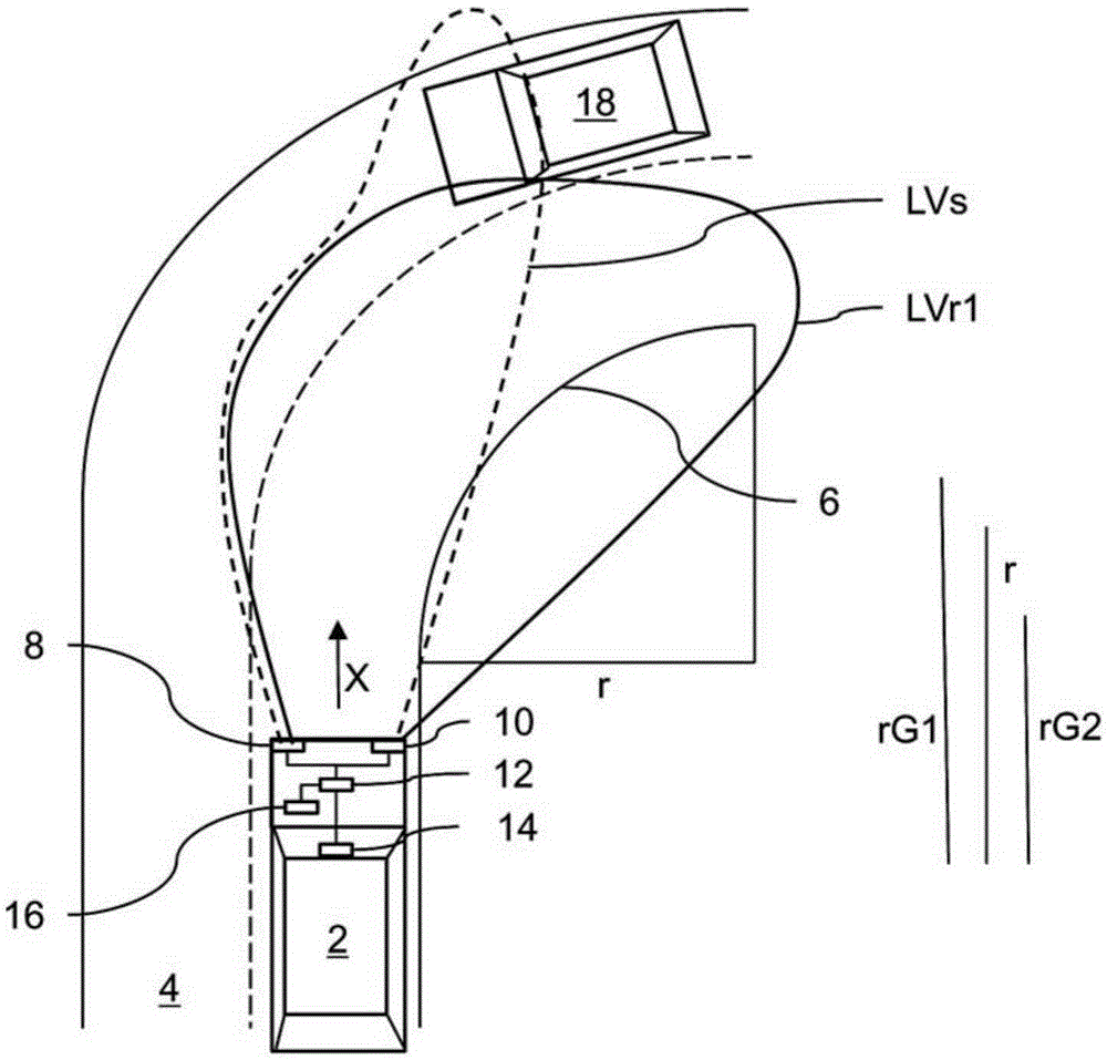
[0039] figure 1 A plan view of motor vehicle 2 on road 4 is shown.

[0040] The motor vehicle 2 travels in the direction of travel X. In this direction there is a right curve 6 ahead in the direction of travel. The right curve 6 has a curve radius R which is smaller than the critical curve radius rG1 but larger than the critical curve radius rG2 .

[0041] Motor vehicle 2 has two headlights 8 , 10 . These headlights 8, 10 are matrix headlights. These headlights 8 , 10 are connected to a control device 12 which controls the light distribution of the headlights 8 , 10 . A plurality of light distributions can thus be adjusted, two of which are shown here, a standard high-beam distribution LVs and a first-stage right-curve high-beam distribution LVr1 . Other light distributions are also possible, for example wider turning light distributions, not shown, for narrower curves.

[0042] The control device 12 is also connected to a camera 14 which monitors an area in the directio...


PUM


Abstract

A motor vehicle headlight and method for operating the headlight is disclosed, wherein the headlight is operated in a main beam mode or in a partial main beam node. A light distribution of the main beam of the headlight is adapted as a function of a course of a road which is being travelled along by the motor vehicle. In addition, a motor vehicle headlight is described.

Description

technical field [0001] A method for operating a headlight of a motor vehicle and a headlight of a motor vehicle are described below. The headlights can be operated in high beam mode or partial high beam mode. Background technique [0002] Headlights of the aforementioned type are known from the prior art. Known headlights are capable of operating in multiple modes. It is known that the headlights can be operated in a low beam mode which has a limited effective range so as not to dazzle oncoming traffic. In addition, most headlights can also be operated in high-beam mode, in which a longer and more powerful range is achieved with a smaller light cone angle. In addition, the relatively narrow high beam distribution should reduce obstruction or impact on oncoming traffic through glare. [0003] In addition, so-called turn signals are known, ie motor vehicle headlights which change their direction of illumination in the direction of the inside of the curve when driving in a ...

Claims


Application Information

Patent Timeline
IPC IPC(8): B60Q1/08
CPCB60Q1/12B60Q1/143B60Q2300/322B60Q2300/40B60Q1/08B60Q2300/32F21S41/60F21S43/00
Inventor F.兰卡贝尔R.哈伯肯P.罗克尔T.费德J.伊利厄姆M.拉伯I.施奈德I.沃尔费尔施奈德
Owner GM GLOBAL TECH OPERATIONS LLC
Learn More