
A el test circuit with protection components

A technology for testing circuits and components, applied in the monitoring of photovoltaic systems, photovoltaic power generation, electrical components, etc., can solve problems such as diode breakdown, and achieve the effect of good effect, good protection effect, and easy breakdown.

Inactive Publication Date: 2018-08-21
CEEG SHANGHAI SOLAR SCI & TECH
View PDF6 Cites 0 Cited by
  • Summary
  • Abstract
  • Description
  • Claims
  • Application Information

AI Technical Summary

Problems solved by technology

Assuming that the impedance uniformity of the diode is consistent, when the voltage is greater than 150V, the diode will break down

Method used


Image

  • A el test circuit with protection components
  • A el test circuit with protection components
  • A el test circuit with protection components

Examples


Embodiment 1

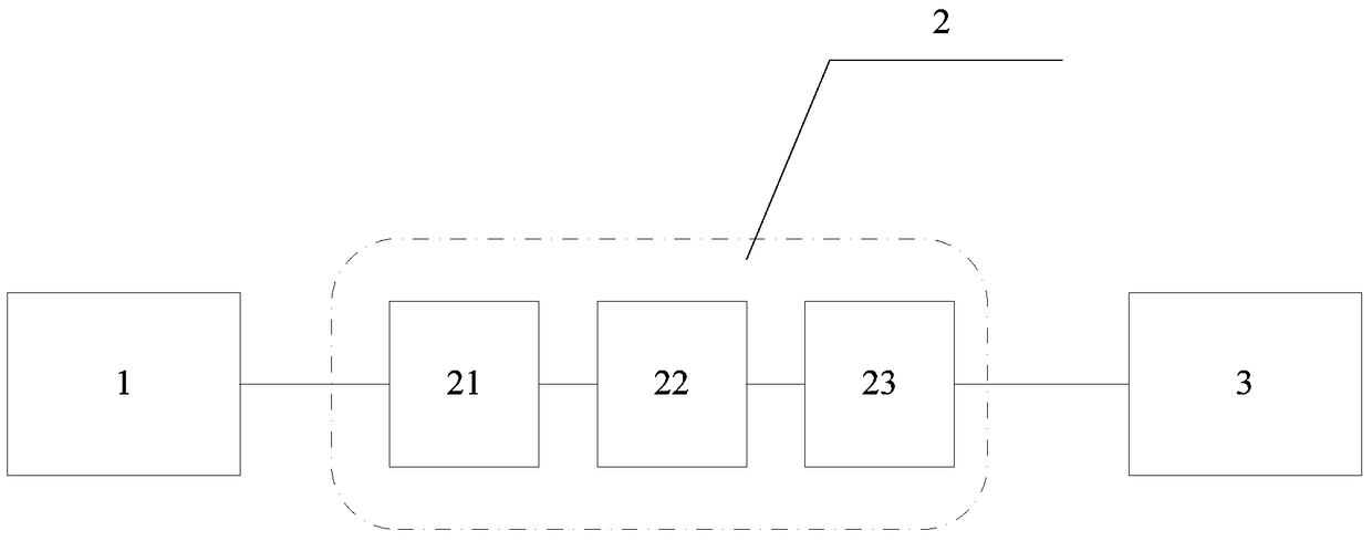
[0026] An EL test circuit with a protection component, which is used to prevent the junction box diode 3 from being broken down during the EL test, such as figure 2 As shown, it includes a power supply 1 and a protection component 2. The protection component consists of a first protection unit 21, a linkage contact switch 22 and a second protection unit 23 connected in sequence. The first protection unit 21 is connected to the power supply 1, and the second protection unit 23 is connected to the Junction box diode 3 connection.

[0027] The power supply 1 is a DC power supply.

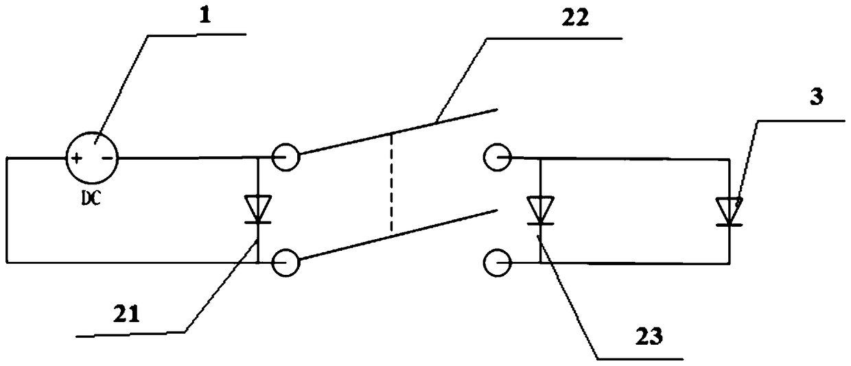
[0028] Such as image 3 As shown, both the first protection unit 21 and the second protection unit 22 are protection diodes, the cathode of the first protection unit 21 is connected to the positive pole of the power supply 1, the anode is connected to the negative pole of the power supply 1, and the cathode of the second protection unit 22 is connected through linkage The contact switch 22 is connec...

Embodiment 2

[0034] The similarities between this embodiment and the first embodiment will not be described, and only the differences will be described.

[0035] In this embodiment, the first protection unit 21 and the second protection unit 22 both include a protection diode, a delay coil and a delay circuit breaker connected in sequence;

[0036] Wherein, the cathode of the protection diode of the first protection unit 21 is connected with the positive pole of power supply 1, and the anode is connected with delay circuit breaker through delay coil, and delay circuit breaker is also connected with the negative pole of power supply 1; The protection of second protection unit 23 The cathode of the diode is connected to the positive pole of the power supply 1 through the linkage contact switch 22, the anode is connected to the delay circuit breaker through the delay coil, and the delay circuit breaker is also connected to the negative pole of the power supply 1 through the linkage contact swi...


PUM


Abstract

The present invention relates to an EL test circuit with a protective component. The test circuit is used for preventing the breakdown of a junction box diode in an EL test. The test circuit comprises a power supply, a protective component which is formed by a first protective unit, a link contact switch and a second protective unit which are connected in order. The first protective unit is connected to the power supply, and the second protective unit is connected to the junction box diode. Compared with the prior art, the EL test circuit has the advantages that the breakdown of the junction box diode in the protective component when EL equipment generates inrush current can be prevented, and at the same time the protection effect is better when two EL test circuits are connected at two sides of a switch.

Description

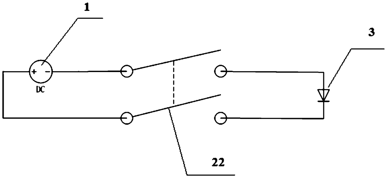
technical field [0001] The invention relates to an EL test circuit, in particular to an EL test circuit with a protection component. Background technique [0002] The junction box is very important in the composition of solar modules. Its main function is to connect the electricity generated by the solar cells with the external circuit. The bypass diode directly affects the electrical performance of the module and the reliability of the hot spot of the battery. Our company has incomplete statistics In 2012, several thousand diodes failed only on the client side; 623 failed inside the factory. When the potting glue junction box is introduced into mass production, the rework due to diode failure will affect the scratches on the backplane, resulting in secondary repairs. And the failure of diodes in the process of customer inspection or on the client side will seriously affect the confidence in our products. At present, the EL tester circuit used in the factory is as follows:...

Claims


Application Information

Patent Timeline
Patent Type & Authority Patents(China)
IPC IPC(8): H02S50/10
CPCY02E10/50
Inventor 李克敏王鹏肖建军
Owner CEEG SHANGHAI SOLAR SCI & TECH
Learn More