Circuit board-based multi-leaf collimator motor lead fixing structure

A multi-leaf collimator and circuit board technology, applied in electrical components, electromechanical devices, electric components, etc., can solve the problems of accuracy and reliability affecting motor movement, poor wiring workmanship, signal interference, etc., and improve detection accuracy. and control stability, structural design and circuit design optimization, and the effect of improving accuracy and anti-interference

Active Publication Date: 2016-06-22
江苏高同装备有限公司
View PDF4 Cites 2 Cited by
  • Summary
  • Abstract
  • Description
  • Claims
  • Application Information

AI Technical Summary

Problems solved by technology

[0013] 1. There are a large number of motors, and the wiring process is poor during the manufacturing and maintenance process. If one of the motors is damaged, the overall wiring harness must be disassembled, the damaged motor must be repaired and replaced, and then all the wiring harnesses must be re-fixed;
[0014] 2. Many signal lines are irregularly arranged in the power line, which causes the signal transmitted inside the signal line to be interfered, which affects the accuracy and reliability of the motor movement, thus affecting the working reliability of the multi-page collimator machine;
[0015] 3. The traditional overall wire binding scheme has structural limitations and cannot meet the structural requirements of the multi-page grating driven by the permanent magnet linear motor, that is, it is impossible to bind the motor mover to form a series of motors larger than the motor stator

Method used


Image

  • Circuit board-based multi-leaf collimator motor lead fixing structure
  • Circuit board-based multi-leaf collimator motor lead fixing structure
  • Circuit board-based multi-leaf collimator motor lead fixing structure

Examples


Embodiment Construction

[0031] A circuit board-based multi-leaf collimator motor lead wire fixing structure designed by the present invention is further described in conjunction with the accompanying drawings and embodiments as follows:

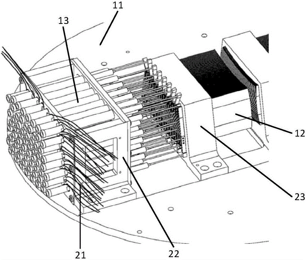
[0032] The circuit board-based multi-leaf collimator motor lead wire fixing structure of the present invention is as follows Figure 4 As shown, wherein the multi-leaf collimator has the same structure as the traditional multi-leaf collimator, including a frame 11, a tungsten alloy blade assembly 12 installed on the frame, and a driving micro-motor array 13 connected with the tungsten alloy blade group 12, Motor array support 22; The lead wire 21 of every miniature motor (as figure 2 shown) and lead structure. The difference lies in that the motor lead wire structure of the present invention is different from that of the traditional multi-leaf collimator motor lead wire structure. The motor lead wire structure of the multi-leaf collimator of the present invention...


PUM


Abstract

The invention relates to a circuit board-based multi-leaf collimator motor lead fixing structure, which belongs to the technical field of mechanical structure design. The multi-leaf collimator motor lead structure adopts two fixed circuit boards; each fixed circuit board comprises a lead fixing hole, a rotor reservation hole and a lead pad arranged on the fixed circuit board, a Hall signal conversion circuit, a peripheral cable interface and a fixing mounting hole arranged on the circuit board and a connection lead; the two fixed circuit boards are vertically fixed at two ends of a rack respectively, and each micro DC motor rotor, a motor power lead and a motor signal output lead tail end are respectively welded on the lead pad on the periphery of the lead fixing hole; and the fixed circuit board is fixed behind a motor frame via the fixing mounting hole, and after the motor power lead and the signal output lead are connected to the Hall signal conversion circuit via the connection lead of the circuit board, the leads are then connected onto the peripheral cable interface. The structure of the invention improves the anti-interference performance of the sensor signal and the sensor precision.

Description

technical field [0001] The invention belongs to the technical field of mechanical structure design, and in particular relates to the improvement of the electrical interconnection structure of motor lead wires in a multi-leaf collimator. Background technique [0002] Multi-leaf collimators are mechanical moving parts used to generate conformal radiation fields, commonly known as multi-leaf gratings, multi-leaf diaphragms, MLC (Multi-Leaf Collimator), etc. Multi-leaf collimators are widely used in the medical field. The core part of the equipment relies on the multi-page collimator to realize the conformal shaping of the rays. According to the movement mode of the multi-leaf collimator, there are two types of multi-leaf collimators: manual and electric. The function of the latter is much greater than that of the former, which is the main form and research and development direction in application; [0003] The structure of the existing multi-page collimator is as follows figu...

Claims


Application Information

Patent Timeline
Patent Type & Authority Applications(China)
IPC IPC(8): H02K5/22H02K29/08
CPCH02K5/225H02K29/08
Inventor 李炳燃叶佩青张辉
Owner 江苏高同装备有限公司
Why Eureka
Try Eureka