Adhesive material, flexible module, display equipment and manufacturing method of flexible module
A technology for display equipment and manufacturing methods, applied to chemical instruments and methods, adhesives, electronic equipment, etc., can solve problems such as inapplicability, damage to the functional film layer of optical adhesive materials, and large bending force, so as to reduce bending stress and benefit Promotion and application, effect of bending stress reduction
- Summary
- Abstract
- Description
- Claims
- Application Information
AI Technical Summary
Problems solved by technology
Method used
Image
Examples
Embodiment 1
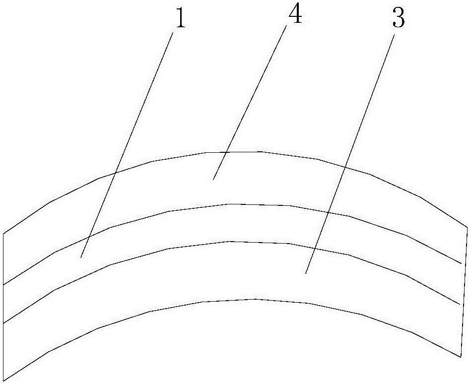
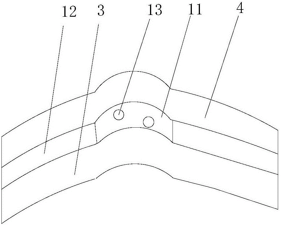
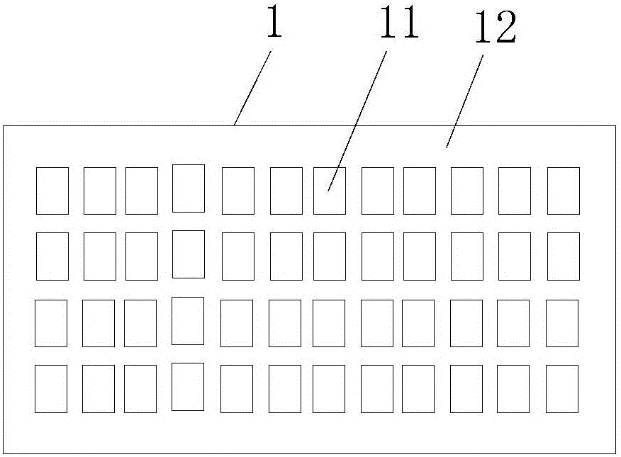
[0042] Such as Figure 2-4 As shown, the adhesive material provided by this embodiment includes an adhesive base layer 1 for being arranged between two modules. The adhesive base layer 1 is divided into a bonding area 12 and a bending load buffer area 11. For bonding two modules, the bending load buffer area 11 is located between the two modules, and the bending stress of the bending load buffer area 11 is smaller than the bending stress of the bonding area 12 . When bending occurs, the bending stress of the bending load buffer zone 11 is smaller than the bending stress of the bonding area 12 . Then when this adhesive material is bonded to two modules, and when bending occurs, for the entire flexible module, the bending stress of the bending load buffer area 11 and its corresponding module parts is smaller than that of the bonding area 12 and its corresponding parts. The corresponding bending stress of the module part. Therefore, for adhesive materials or flexible modules th...
Embodiment 2
[0053] Such as Figure 5 As shown, this embodiment also provides a flexible module, which includes a lower first module part 3 and an upper second module part 4, which also includes the adhesive material in the first embodiment above. The first module part 3 and the second module part 4 are bonded to each other by glue.
[0054] Among them, the first module part 3 includes a graphite sheet 33, a display screen 32, and a circular polarizer 31 arranged sequentially from bottom to top; the second module part 4 includes a touch part 43 and an adhesive layer arranged sequentially from bottom to top. 42 . The protective layer 41 ; wherein, the adhesive material is disposed between the circular polarizer 31 and the touch portion 43 . The adhesive material includes an adhesive base layer 1 arranged between two modules. The adhesive base layer 1 is divided into a bonding area 12 and a bending load buffer area 11. The bending load buffer area 11 is located between the two modules. The...
Embodiment 3
[0057] This embodiment also provides a display device, which includes the flexible module in the second embodiment. The display device uses the flexible module in the second embodiment above.
[0058] The display device includes a display substrate, and the display substrate includes an opaque area; the orthographic projection of the bending load buffer zone 11 on the display substrate on the adhesive base layer is located in the opaque area, that is to say, the adhesive material base layer 1 The bending load buffer zone 11 overlaps with the opaque area of the display substrate in correspondence with each other, and has the effect of not affecting the display effect. At the same time, the display device also has the same beneficial effects as the flexible module in the second embodiment. The display device can be any electrical device that can be applied with a flexible module, such as a mobile phone, a tablet, and a computer.
PUM
 Abstract
Description
Claims
Application Information
 - R&D
- Intellectual Property
- Life Sciences
- Materials
- Tech Scout
- Unparalleled Data Quality
- Higher Quality Content
- 60% Fewer Hallucinations
Browse by: Latest US Patents, China's latest patents, Technical Efficacy Thesaurus, Application Domain, Technology Topic, Popular Technical Reports.
© 2025 PatSnap. All rights reserved.Legal|Privacy policy|Modern Slavery Act Transparency Statement|Sitemap|About US| Contact US: help@patsnap.com


