
Gear with oil distribution tank, electric machine and vehicle

A technology of oil distribution grooves and gears, which is applied to mechanical equipment, components with teeth, gear lubrication/cooling, etc., can solve the problems of not considering the distribution of lubricating oil, reducing the effect of lubricating oil coating, and failing to distribute lubricating oil, etc., to achieve Long service life, reduced gear wear, and improved gear life

Active Publication Date: 2016-06-22
靖江市华信科技创业园有限公司
View PDF5 Cites 9 Cited by
  • Summary
  • Abstract
  • Description
  • Claims
  • Application Information

AI Technical Summary

Problems solved by technology

[0002] Gears are commonly used mechanical parts. There is a lot of friction on the transmission contact surface of the gear, so it is necessary to use lubricating oil. The existing gear design does not consider the distribution of lubricating oil, and the lubricating oil cannot be accurately distributed to the transmission contact surface of the gear. , there is room for improvement
[0003] Even if the traditional gear is immersed in the lubricating oil, the centrifugal effect and cavitation generated by the rotational movement of the gear will reduce the coating effect of the lubricating oil on the transmission contact surface of the gear

Method used


Image

  • Gear with oil distribution tank, electric machine and vehicle
  • Gear with oil distribution tank, electric machine and vehicle
  • Gear with oil distribution tank, electric machine and vehicle

Examples


Embodiment 1

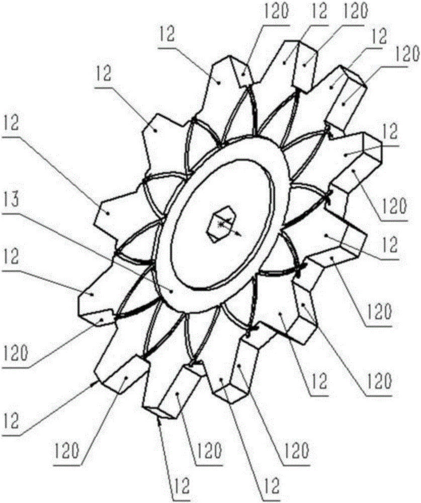
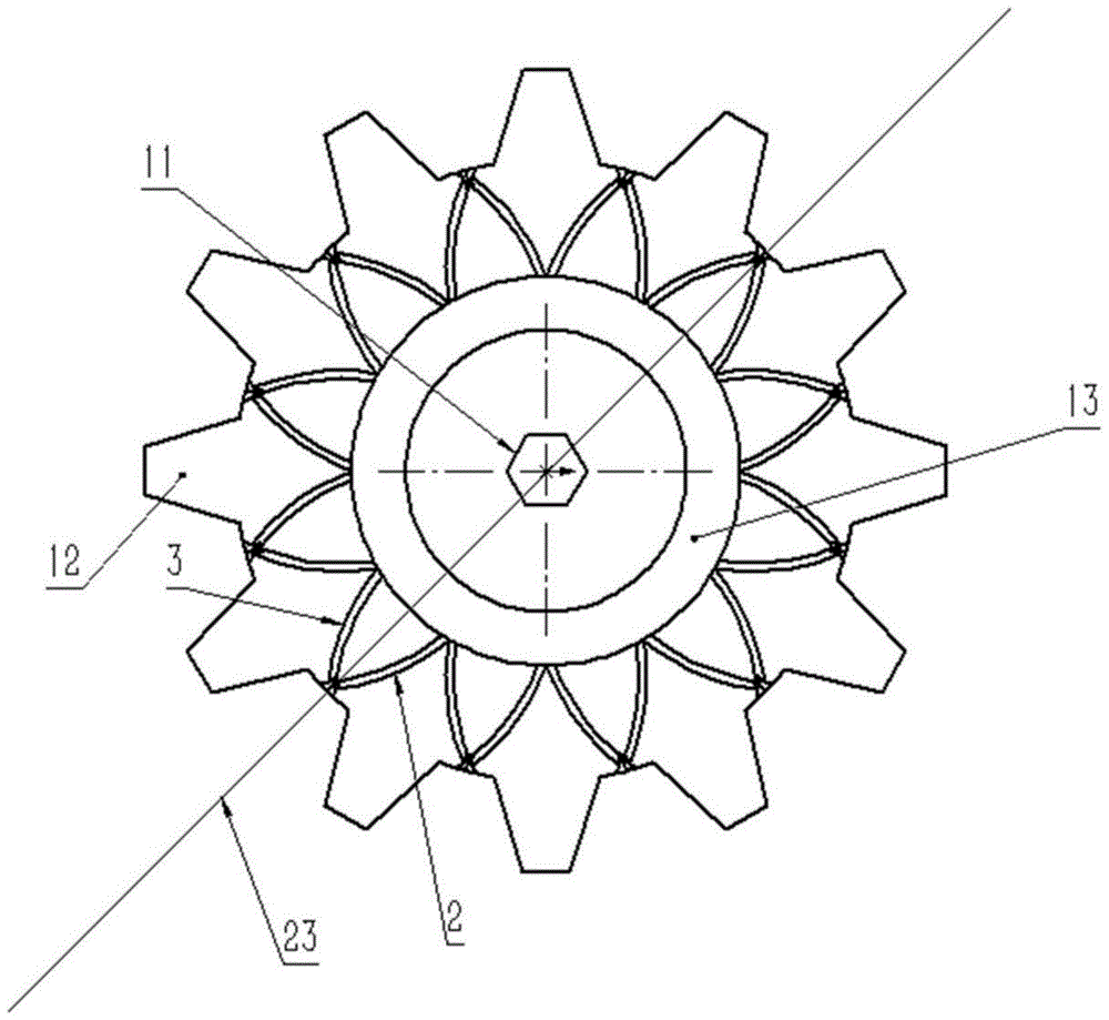
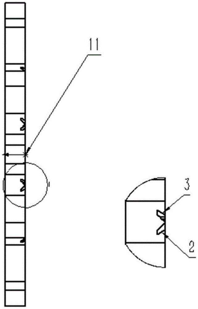
[0028] Implementation example 1, such as Figure 1-3 As shown, the gear with an oil distribution groove includes a main body 1, teeth 12, and a connecting portion 11, and is characterized in that it also includes a first curved groove 2, a second curved groove 3, and a connecting groove 13;

[0029] The clock directions of the tracks formed by the first curved groove 2 and the second curved groove 3 from the inner end to the outer end are different;

[0030] The first curved groove 2 and the second curved groove 3 are distributed in pairs on both sides of the connecting line 23 between the center of the tooth valley of the main body 1 and the axis of the main body 1;

[0031] The outer sides of the paired first curved groove 2 and the second curved groove 3 have openings at the tooth valleys of the main body 1. The function of this design is to allow the liquid in the grooves to flow out from the tooth valleys during the gear rotation. , and then splash on the contact transmi...

Embodiment 2

[0035] Implementation example 2, a gear, on the basis of implementation example 1, both planes have curved grooves.

Embodiment 3

[0036] Implementation example 3, an electric machine, has the gear described in implementation example 1, and the position is fixed during work.


PUM


Abstract

The invention discloses a gear with an oil distribution tank. The gear comprises a main body (1), teeth (12) and a connecting part (11), and is characterized by further comprising a first curve groove (2), a second curve groove (3) and a connecting groove (13); clock directions of trajectories formed by the first curve groove (2) and the second curve groove (3) from inner ends to outer ends are different; the first curve groove (2) and the second curve groove (3) are pairwise distributed on two sides of a connecting line (23) between the center of tooth valleys of the main body (1) and the axis of the main body (1); the outer sides of the pairwise first curve groove (2) and second curve groove (3) are respectively provided with openings in the tooth valley parts of the main body (1); and the inner ends of the first curve groove (2) and the second curve groove (3) are both communicated with the connecting groove (13). An electric machine has the gear with the oil distribution tank. A vehicle has the gear with the oil distribution tank. The gear, the electric machine and the vehicle are low in cost, flexible in application, long in service life and stable.

Description

technical field [0001] The invention belongs to the field of machinery, in particular to gears with oil distribution grooves, electric machinery and automobiles. Background technique [0002] Gears are commonly used mechanical parts. There is a lot of friction on the transmission contact surface of the gear, so it is necessary to use lubricating oil. The existing gear design does not consider the distribution of lubricating oil, and the lubricating oil cannot be accurately distributed to the transmission contact surface of the gear. , there is room for improvement. [0003] Even if the traditional gear is immersed in lubricating oil, the centrifugal effect and cavitation generated by the rotational movement of the gear will reduce the coating effect of the lubricating oil on the transmission contact surface of the gear. [0004] If a gear is designed to accurately distribute the lubricating oil to the transmission contact surface of the gear, it will help to enhance the coa...

Claims


Application Information

Patent Timeline
IPC IPC(8): F16H55/17F16H55/06F16H57/04
CPCF16H55/06F16H55/17F16H57/0431
Inventor 褚婷婷
Owner 靖江市华信科技创业园有限公司
Learn More