
A clamping plate lock

A locker and pressure plate technology, applied in the direction of thin plate connection, friction clamping detachable fasteners, cooling/ventilation/heating transformation, etc., can solve the problems of inconvenient assembly and replacement, easy drop of screws, nuts and washers, etc. To achieve the effect of compaction and reliability

Active Publication Date: 2018-02-06
王付华
View PDF9 Cites 0 Cited by
  • Summary
  • Abstract
  • Description
  • Claims
  • Application Information

AI Technical Summary

Problems solved by technology

The installation between the sub-cooling plate or other components and the main cooling plate usually adopts the traditional screw or bolt nut direct fastening installation method, which makes it extremely inconvenient to assemble and replace the sub-cooling plate or other components, and Screws, nuts, washers, etc. are easy to fall into the chassis, causing hidden dangers

Method used


Image

  • A clamping plate lock
  • A clamping plate lock
  • A clamping plate lock

Examples


Embodiment Construction

[0036] The following will clearly and completely describe the technical solutions in the embodiments of the present invention with reference to the accompanying drawings in the embodiments of the present invention. Obviously, the described embodiments are only some, not all, embodiments of the present invention. Based on the embodiments of the present invention, all other embodiments obtained by persons of ordinary skill in the art without making creative efforts belong to the protection scope of the present invention.

[0037] The purpose of the present invention is to provide a clamping plate type locking device, which can easily assemble and replace sub-cooling plates or other components.

[0038] In order to make the above objects, features and advantages of the present invention more comprehensible, the present invention will be further described in detail below in conjunction with the accompanying drawings and specific embodiments.

[0039] Such as figure 1 , 2 , 3, in...


PUM


Abstract

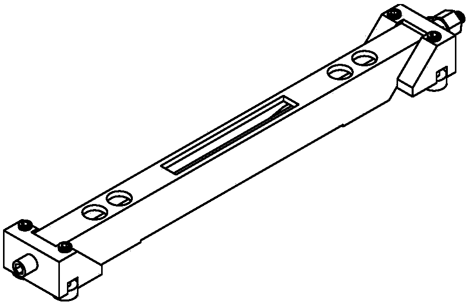
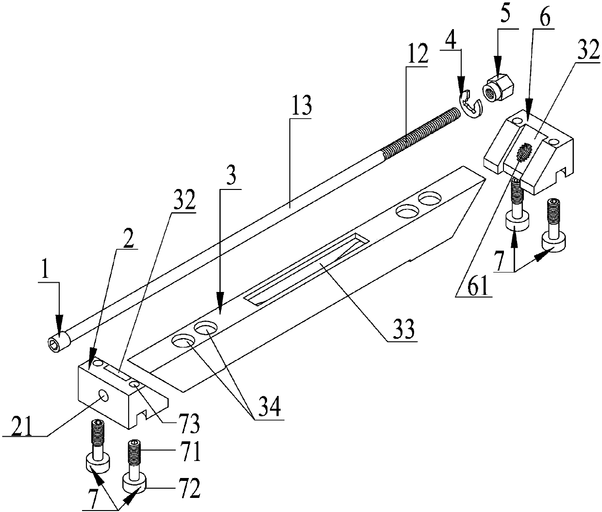
The invention discloses a pressing-plate-type lock which comprises a screw, a front wedge block, a rear wedge block and a fixed wedge block, wherein the front wedge block and the rear wedge block are positioned at the two ends of the fixed wedge block; a first rectangular through hole is formed in the fixed wedge block in the length direction of the fixed wedge block; a spring leaf is mounted on the bottom surface of the first rectangular through hole; a circular through hole is formed in the front wedge block; one end of the screw is a cylindrical head with an inner hexagonal hole; the other end of the screw is a threaded part; the middle of the screw is a polished rod part; a threaded hole matched with the threaded part is formed in the rear wedge block; the front wedge block, the rear wedge block and the fixed wedge block are connected together through the screw; the two end surfaces in the length direction of the fixed wedge block are inclined surfaces which are distributed symmetrically; the end surfaces, where the front wedge block, and the rear wedge block are in contact with the fixed wedge block are matched with the inclined surfaces of the fixed wedge block; the fixed wedge block is fixed on a mother cooling plate in an electronic case; and when the screw is rotated, the front wedge block and the rear wedge block move up and down along with the screw in the first rectangular through hole, and the distances, relative to the mother cooling plate, of the front wedge block and the rear wedge block are changed along with the movement, so that a daughter cooling plate or other components can be compressed or loosened very conveniently.

Description

technical field [0001] The invention relates to the technical field of printed circuit boards, in particular to a fastening device for components inside an electronic cabinet. Background technique [0002] At present, in the standard electronic chassis widely used in the electronic application industry, there are generally two kinds of cooling plates, and the areas of the two cooling plates are different. Compared with the two, the smaller area is the sub-cooling plate, and the larger area is the main cooling plate. The installation between the sub-cooling plate or other components and the main cooling plate usually adopts the traditional screw or bolt nut direct fastening installation method, which makes it extremely inconvenient to assemble and replace the sub-cooling plate or other components, and Screws, nuts, washers, etc. are easy to fall into the chassis and cause hidden dangers. Contents of the invention [0003] The purpose of the present invention is to provide ...

Claims


Application Information

Patent Timeline
Patent Type & Authority Patents(China)
IPC IPC(8): H05K7/20H05K13/04F16B2/06F16B5/06
CPCF16B2/065F16B5/0607H05K7/20H05K13/04
Inventor 王付华
Owner 王付华
Learn More