Unmanned aerial vehicle device with long running time and control method
A technology of endurance time and control method, which is applied in the direction of aircraft control, unmanned aircraft, glider, etc., can solve the problem of inability to carry out ultra-long-distance and long-distance operations, the main propeller's low energy utilization rate, and the increase of drones. Endurance time and other issues, to achieve the effect of reducing airborne energy consumption, improving endurance status, and increasing endurance time
- Summary
- Abstract
- Description
- Claims
- Application Information
AI Technical Summary
Problems solved by technology
Method used
Image
Examples
Embodiment 1
[0036] This embodiment is used for the take-off stage of the UAV and the gliding stage after take-off when the UAV performs a long-distance and long-term flight mission.
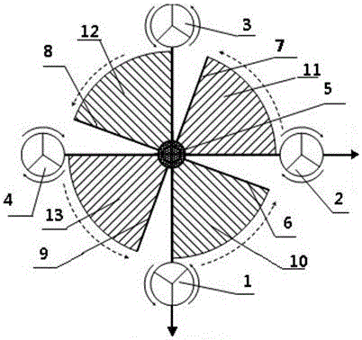
[0037] Such as figure 2 As shown, the UAV device with high endurance time includes a frame and a main propeller. The main propeller is symmetrically arranged in four directions of the frame, and a main control unit for controlling the flight state of the UAV is also installed on the frame. The UAV device also includes a wing gliding device and a driving device 5, the wing gliding device is connected with the driving device 5, and the driving device 5 controls the wing gliding device to expand or retract.
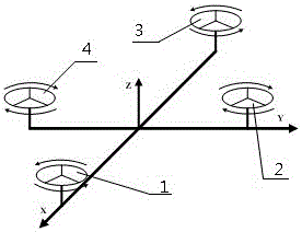
[0038] The four main propellers are arranged symmetrically in the front, rear, left and right directions of the frame, and the layout plane of the cross-shaped frame is regarded as a Cartesian coordinate plane, then the first main propeller 1 and the third main propeller 3 are respectively arranged on the...
Embodiment 2
[0046] This embodiment is used for the gliding phase of the UAV when the UAV performs long-distance and long-term flight missions.
[0047] Such as figure 2 As shown, the UAV device with high endurance time includes a frame and a main propeller. The main propeller is symmetrically arranged in four directions of the frame, and a main control unit for controlling the flight state of the UAV is also installed on the frame. The unmanned aerial vehicle device also includes a wing gliding device and a driving device 5, and the wing gliding device is connected with the driving device 5, and the driving device 5 controls the wing gliding device to expand or retract, so that no one is present after the wing gliding device is opened. The machine can glide in the air with the help of wings.
[0048] The wing gliding device includes a rotating shaft and a wing, and the UAV device in this embodiment is equipped with 4 wings and corresponding 4 rotating shafts, which are respectively symm...
Embodiment 3
[0058] This embodiment is used for the landing stage of the UAV when the UAV performs long-distance and long-term flight missions.
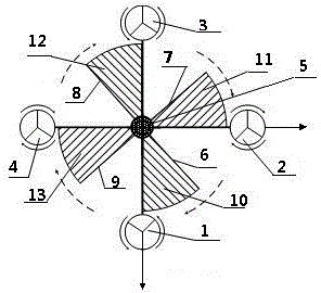
[0059] When the UAV is ready to land, first adjust the flight direction of the UAV through the auxiliary propeller, so that the UAV glides and descends slowly on the track that needs to land. When approaching the sky above the landing destination, the driving device 5 is controlled by the main control unit, such as image 3 As shown, the main control unit controls the driving device 5 to work, so that the driving shaft rotates to drive the four rotating shafts to rotate clockwise, so that the four wings also rotate clockwise and are folded. At the same time, the main propeller provides power for the drone. Land the drone safely. A groove structure for accommodating the rotating shaft and the wings is provided on the frame. When the UAV takes off or lands, the rotating shaft rotates with the driving device to draw in the wings, and the grooves o...
PUM
 Abstract
Description
Claims
Application Information
 - Generate Ideas
- Intellectual Property
- Life Sciences
- Materials
- Tech Scout
- Unparalleled Data Quality
- Higher Quality Content
- 60% Fewer Hallucinations
Browse by: Latest US Patents, China's latest patents, Technical Efficacy Thesaurus, Application Domain, Technology Topic, Popular Technical Reports.
© 2025 PatSnap. All rights reserved.Legal|Privacy policy|Modern Slavery Act Transparency Statement|Sitemap|About US| Contact US: help@patsnap.com


