Bicycle

A bicycle and frame technology, which is applied in the field of bicycle manufacturing, can solve the problems of not being able to drive the crankset and riding hard, and achieve the effect of convenient riding and easy exertion

Active Publication Date: 2016-06-22
河北铁牛自行车业有限公司
View PDF6 Cites 2 Cited by
  • Summary
  • Abstract
  • Description
  • Claims
  • Application Information

AI Technical Summary

Problems solved by technology

When the bicycle of the present invention is in use, the pedals can quickly transition from a state where it is difficult to exert force to a state where it is easy to exert force. When the pedals are close to the plumb line, that is to say, when the pedals are generally distributed upwards, When the clutch structure is switched to the off position, the rotating shaft cannot drive the crankshaft, and the rotating shaft is idling without bearing the load. The pedal quickly leaves the plumb line and transitions to a state where it is easy to exert force. The disc rotates, so it can be seen that when the rotating bearing is loaded, the pedal has left the plumb line, which overcomes the shortcoming of bicycle riding.

Method used


Image

  • Bicycle
  • Bicycle
  • Bicycle

Examples


Embodiment 1

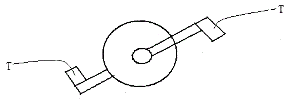
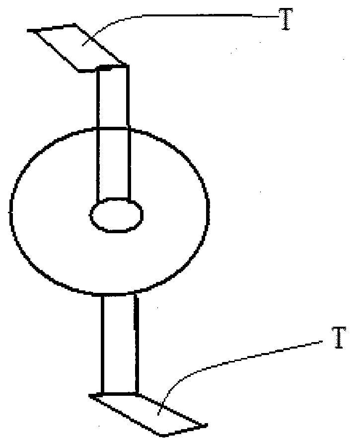
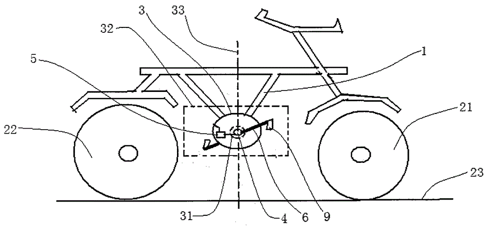
[0017] A bicycle, comprising a vehicle frame 1, a front wheel 21, a rear wheel 22, a crankshaft 3, and a rotating shaft 4, a clutch structure 5, and two connecting rods 6; the center of the crankshaft 3 is provided with a circular hole 31, and the crankshaft 4 runs through the round hole 31, the two ends of the rotating shaft 4 are respectively connected to the head end of a connecting rod 6, and the tail end of the connecting rod 6 is provided with a pedal 9; the plane formed by the extension of the tooth plate 3 is called vertical Face 32, the projection of two pedals 9 on vertical surface 32, wherein one is positioned at circular hole 31 one side, and another is positioned at the opposite side of circular hole 31; The straight line cut is called the horizon 23, and the straight line passing through the center of the tooth plate 3 and perpendicular to the horizon 23 is called the plumb line 33; the clutch structure 5 is arranged between the rotating shaft 4 and the tooth plat...

Embodiment 2

[0021] A bicycle, comprising a vehicle frame 1, a front wheel 21, a rear wheel 22, a crankshaft 3, and a rotating shaft 4, a clutch structure 5, and two connecting rods 6; the center of the crankshaft 3 is provided with a circular hole 31, and the crankshaft 4 runs through the round hole 31, the two ends of the rotating shaft 4 are respectively connected to the head end of a connecting rod 6, and the tail end of the connecting rod 6 is provided with a pedal 9; the plane formed by the extension of the tooth plate 3 is called vertical Face 32, the projection of two pedals 9 on vertical surface 32, wherein one is positioned at circular hole 31 one side, and another is positioned at the opposite side of circular hole 31; The straight line cut is called the horizon 23, and the straight line passing through the center of the tooth plate 3 and perpendicular to the horizon 23 is called the plumb line 33; the clutch structure 5 is arranged between the rotating shaft 4 and the tooth plat...


PUM


Abstract

The invention discloses a bicycle. The bicycle comprises a bicycle frame, a front wheel, a rear wheel and a chain wheel, and further comprises a rotary shaft, a clutch structure and two connecting rods, wherein a round hole is formed in the center of the chain wheel; the rotary shaft penetrates through the round hole; the two ends of the rotary shaft are connected with the head ends of the two connecting rods correspondingly; the tail end of each connecting rod is provided with a pedal; the straight line tangential to both the bottom of the front wheel and the bottom of the rear wheel is called as a horizon line, and the straight line passing through the center of the chain wheel and also vertically intersecting with the horizon line is called as a plumb line; the clutch structure is arranged between the rotary shaft and the chain wheel; the rotary shaft can drive the chain wheel when the clutch structure is in the engaged position, but not when the clutch structure is in the disengaged position; and the clutch structure is switched to be at the disengaged position when the pedals are close to the plumb line, and is switched to the engaged position when the pedals are away from the plumb line. The bicycle has the following advantages of exerting force easily and being convenient to ride.

Description

technical field [0001] The invention relates to the field of bicycle manufacturing Background technique [0002] Bicycle can be seen everywhere as a kind of walking-replacing tool, and bicycle generally comprises vehicle frame, front wheel, trailing wheel, chainring, but the bicycle of prior art has a common shortcoming: riding is laborious, not very convenient, as figure 1 As shown, when the two pedals T of the bicycle are distributed forward and backward, it is easy for the rider to exert force on the pedals, as long as he pushes the pedals T with his feet, and the movements are very natural and coordinated, as shown in figure 2 As shown, when the two pedals T of the bicycle are distributed upwards and downwards, it is difficult for the rider to exert force on the pedals T, and the rider must make the following actions: the left foot pushes one pedal T forward , the sole of the right foot pushes the other pedal T backward, the sole of the left foot forms an acute angle w...

Claims


Application Information

Patent Timeline
IPC IPC(8): B62M1/36B62M23/00
Inventor 叶大可
Owner 河北铁牛自行车业有限公司
Why Eureka
Try Eureka