
Plank cutting and edge trimming device

A technology for wood boards and base plates, which is applied in the field of wood board cutting edge trimming devices, can solve the problems of complex process, low processing precision, and inflexibility, etc., and achieves the effects of operator safety, good cutting effect and high safety factor.

Inactive Publication Date: 2016-06-22
WUXI FORMEN TECHN
View PDF0 Cites 12 Cited by
  • Summary
  • Abstract
  • Description
  • Claims
  • Application Information

AI Technical Summary

Problems solved by technology

[0002] When traditional wood boards are cut, one end is usually cut with a cutting saw blade. After cutting one end, it needs to be pushed again to cut the other end. The disadvantage is that the two ends are not uniform after cutting. This processing method has processing Insufficient precision, complex process, uneven product quality and other defects reduce work efficiency, increase labor, increase work costs, and cause unnecessary waste. In addition, the saw blade has no protective measures and is exposed to the outside. They are not very safe; there is no propulsion device designed. In the cutting operation process, manual operation is required, which is not flexible enough. When the manual operation is used to push the wooden board for cutting, the direction of the thrust is not fixed, and the wooden board is not pressed tightly, which is easy to cause trimming. Unevenness and low processing precision, so it is necessary to design a plank cutting and trimming device for finishing, so that the ends of the plank are neat after cutting

Method used


Image

  • Plank cutting and edge trimming device
  • Plank cutting and edge trimming device
  • Plank cutting and edge trimming device

Examples


Embodiment Construction

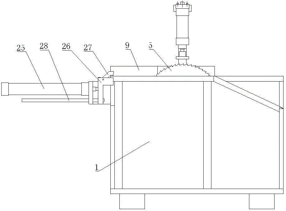
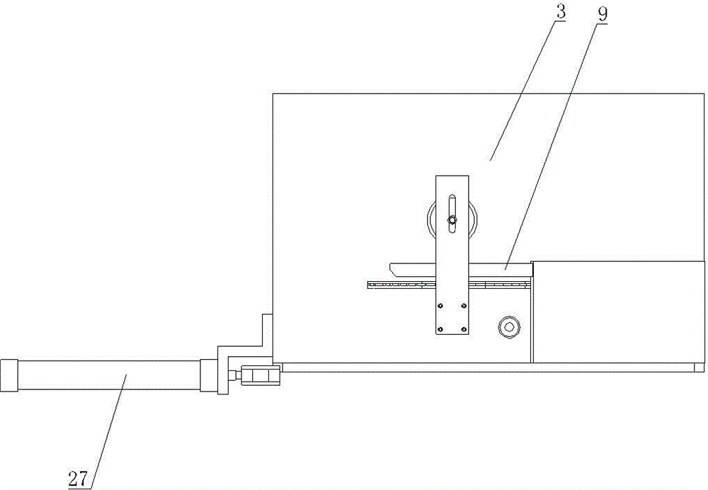
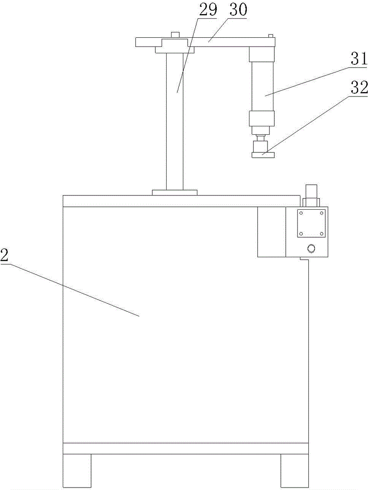
[0021] Such as figure 1 , figure 2 , image 3 , Figure 4 , Figure 5 , Image 6 , Figure 7 , Figure 8 , including a base 1, the base 1 includes a mounting box 2, a bottom plate 3 is arranged on the mounting box 2, a saw blade 5 driven by a motor 4, and a cylinder for lifting the saw blade 5 are arranged in the mounting box 2 (not shown in the figure ), the positioning cylinder 7 connected with the positioning block 6, and the bottom plate 3 are respectively provided with a saw groove 8 and a positioning hole 9 for the saw blade 5 and the positioning block 6 to pass through. Plate 9, on the outside of the base plate 3 corresponding to the limit plate 9 is also provided with a pressing mechanism, the rear end of the base plate 3 is also provided with a pushing mechanism, on the base 1, a rear slide plate 10 is provided on the rear side corresponding to the saw groove 8 , the rear end of the rear slide 10 is inclined downward;

[0022] The installation box 2 is provid...


PUM


Abstract

The invention provides a plank cutting and edge trimming device. The device is simple in structure; manual pushing is replaced; and a plank can be cut, fixed and positioned conveniently, so that the cutting effect is excellent, the operation is convenient, the security coefficient is high, and cut edges are enabled to be flush. The device comprises a base, wherein the base comprises an installation box; a base plate is arranged on the installation box; a saw blade, a cylinder and a positioning cylinder are arranged inside the installation box; the saw blade is driven by an electric motor; the cylinder is used for raising the saw blade; the positioning cylinder is connected with a positioning block; a saw groove and a positioning hole which allow the saw blade and the positioning block to pass through are formed in the base plate; a limiting plate is arranged at the outer side of the saw groove and is parallel to the saw groove; a pressing mechanism is also arranged corresponding to the outer side of the limiting plate on the base plate; a pushing mechanism is also arranged at the rear end of the base plate; a rear sliding plate is arranged corresponding to the rear side of the saw groove on the base; and the rear end of the rear sliding plate inclines downwards.

Description

technical field [0001] The invention relates to the technical field of wood cutting equipment, in particular to a wood cutting edge trimming device. Background technique [0002] When traditional wood boards are cut, one end is usually cut with a cutting saw blade. After cutting one end, it needs to be pushed again to cut the other end. The disadvantage is that the two ends are not uniform after cutting. This processing method has processing Insufficient precision, complex process, uneven product quality and other defects reduce work efficiency, increase labor, increase work costs, and cause unnecessary waste. In addition, the saw blade has no protective measures and is exposed to the outside. They are not very safe; there is no propulsion device designed. In the cutting operation process, manual operation is required, which is not flexible enough. When the manual operation is used to push the wooden board for cutting, the direction of the thrust is not fixed, and the wooden...

Claims


Application Information

Patent Timeline
IPC IPC(8): B27B5/04B27B5/18B27B25/00B27B29/02
Inventor 田芸
Owner WUXI FORMEN TECHN
Learn More