Current mode synchronous rectification PWM control circuit
A control circuit and synchronous rectification technology, applied in the direction of converting AC power input to DC power output, electrical components, output power conversion devices, etc. The effect of simple circuit structure and high output voltage accuracy
- Summary
- Abstract
- Description
- Claims
- Application Information
AI Technical Summary
Problems solved by technology
Method used
Image

Examples
Embodiment
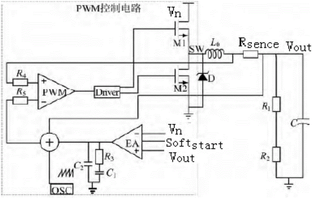
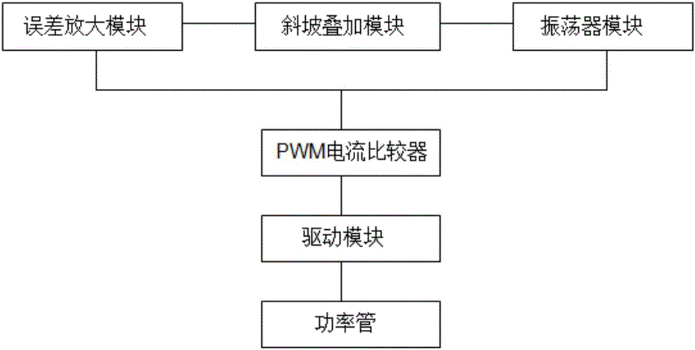
[0015] A current mode synchronous rectification PWM control circuit, the current mode synchronous rectification PWM control circuit includes an error amplification module, a PWM comparison module, a current sampling amplification module, an oscillator module and a drive module, the error amplification module and the oscillator module and The PWM comparison module is connected, the error amplification module generates the output voltage of the error amplifier through the feedback resistor, and the output voltage and the sawtooth wave signal generated by the oscillator module are superimposed as the input signal of the PWM comparison module, and the current sampling amplification module Connected with the PWM comparison module, the current sampling amplification module generates the output signal of the current loop by detecting the output current, and inputs it to the other end of the PWM comparison module, and the drive module is also connected with the PWM comparison module. C...
PUM
 Abstract
Description
Claims
Application Information
 - R&D
- Intellectual Property
- Life Sciences
- Materials
- Tech Scout
- Unparalleled Data Quality
- Higher Quality Content
- 60% Fewer Hallucinations
Browse by: Latest US Patents, China's latest patents, Technical Efficacy Thesaurus, Application Domain, Technology Topic, Popular Technical Reports.
© 2025 PatSnap. All rights reserved.Legal|Privacy policy|Modern Slavery Act Transparency Statement|Sitemap|About US| Contact US: help@patsnap.com