Motor for turbocharger

A technology for turbochargers and electric motors, which is applied in the direction of electric components, electrical components, electromechanical devices, etc., can solve the problems of unretrieved permanent magnet fixing research reports, etc., and achieve the goal of improving low-speed supercharging effect and improving fuel utilization rate Effect

Active Publication Date: 2018-01-16
SHANDONG UNIV OF TECH
View PDF4 Cites 0 Cited by
  • Summary
  • Abstract
  • Description
  • Claims
  • Application Information

AI Technical Summary

Problems solved by technology

[0010] At present, the applicant has not yet retrieved research reports on fixing the permanent magnet on the side of the turbocharger and away from the exhaust gas turbine

Method used


Image

  • Motor for turbocharger
  • Motor for turbocharger
  • Motor for turbocharger

Examples


specific Embodiment approach

[0043] The invention will be described in further detail below in conjunction with the accompanying drawings.

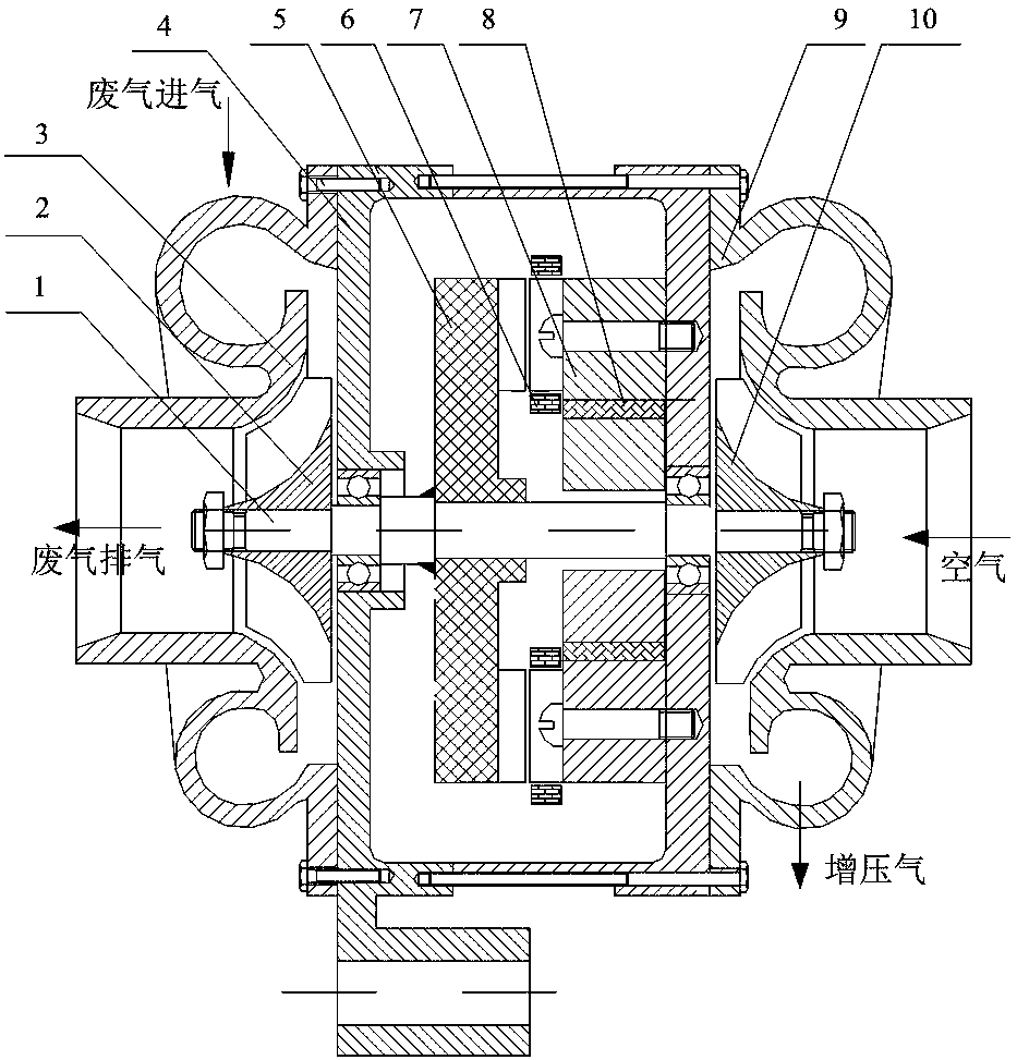
[0044] figure 1 It is a longitudinal sectional view of a turbocharger motor of the present invention.

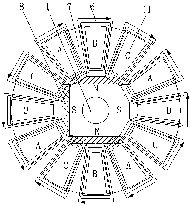
[0045] A motor for a turbocharger consists of a shaft (1), an exhaust gas turbine (2), an exhaust gas turbine casing (3), a motor casing (4), a rotor core (5), an armature winding (6), and a stator core (7) , a permanent magnet (8), a turbocharger casing (9) and a turbocharger (10);

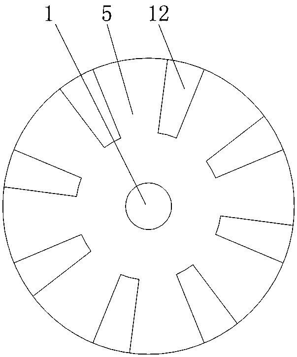
[0046] Both ends of the shaft (1) are respectively fixed with an exhaust gas turbine (2) and a turbocharger (10), and the middle of the shaft (1) is fixed with a disc-shaped rotor core (5);

[0047] The rotor core (5) has a rotor pole protruding in the axial direction on one axial end surface; the rotor pole is fan-shaped;

[0048] Between the rotor pole and the motor housing (4) is a disc-shaped stator core (7), the stator core (7) is fixed on the inner wall of the motor housing (...


PUM


Abstract

A motor for a turbocharger is composed of a shaft, an exhaust gas turbine, an exhaust gas turbine housing, a motor housing, a rotor iron core, an armature winding, a stator iron core, a permanent magnet, a supercharging turbine housing and a supercharging turbine. The two ends of the shaft are respectively fixed with an exhaust gas turbine and a turbocharger, and a disc-shaped rotor core is fixed in the middle of the shaft, and one end surface of the rotor core has a rotor pole protruding in the axial direction. The stator core is fixed on the inner wall of the motor casing; the end face of the stator core facing the rotor core has axially protruding stator poles. The armature windings are wound around the stator poles. A permanent magnet is embedded in the stator iron core inside the circumference formed by every three stator poles. The technical rotor of the present invention has no permanent magnets and excitation windings, and can adapt to the high temperature and high speed working environment where the exhaust gas turbine is located; the permanent magnets and armature windings are located on the stator, which is conducive to centralized heat dissipation; it can be used as a motor to realize turbocharging , and can also be used as a generator to recover exhaust gas energy.

Description

technical field [0001] The invention relates to a motor for a turbocharger, which belongs to the technical field of automobile electric appliances. Background technique [0002] At present, the thermal efficiency of most engines is below 35%. The high-temperature and high-pressure exhaust gas emitted by the engine takes away 40% of the heat energy of the fuel. Most engines cannot effectively use this energy. The exhaust gas turbocharging device realizes the utilization of part of the kinetic energy of the exhaust gas, improves the fuel utilization rate of the engine, and is currently being used more and more widely. [0003] In addition, the exhaust gas turbocharging device has a certain time-lag effect, that is, its speed is low when the engine is just started, and it cannot effectively provide supercharging. Only when the engine speed reaches 2000 rpm, the supercharging effect is more obvious. Therefore, adding an electric motor to the exhaust gas turbine and rapidly inc...

Claims


Application Information

Patent Timeline
Patent Type & Authority Patents(China)
IPC IPC(8): H02K1/14H02K1/17H02K1/24H02K7/18
CPCH02K1/14H02K1/17H02K1/24H02K7/1823
Inventor 史立伟马永坤章振浩张学义马良李金浩聂秀吉
Owner SHANDONG UNIV OF TECH
Why Eureka
Try Eureka