
Antenna fixing apparatus for strengthening concentrator signal

An antenna fixing device and concentrator technology, which is applied to antenna supports/installation devices, antennas, antenna parts, etc., can solve the problems of affecting the reception and transmission of collected signals, the difficulty of fixing the magnetic antenna, and the low collection success rate. Improve the success rate of acquisition, enhance transmission and reception, and improve the effect of signal reception

Inactive Publication Date: 2016-06-15
ZHANGQIU POWER SUPPLY CO OF STATE GRID SHANDONG ELECTRIC POWER CO +1
View PDF8 Cites 2 Cited by
  • Summary
  • Abstract
  • Description
  • Claims
  • Application Information

AI Technical Summary

Problems solved by technology

However, in actual use, the meter box is mostly made of plastic, and there is no metal material to absorb it. The antenna of the data collector is a magnetic suction cup. The original intention of the design is to absorb metal products for fixing, and it is easy to move, so the magnetic antenna is not easy to fix.
Antennas are either placed directly in the meter box, or directly wrapped around lines and other accessories, causing potential safety hazards
At the same time, the meter boxes are mostly installed in areas with relatively weak signals such as corridors and hanging corners, which affect the reception and transmission of collected signals, resulting in a low collection success rate

Method used


Image

  • Antenna fixing apparatus for strengthening concentrator signal
  • Antenna fixing apparatus for strengthening concentrator signal
  • Antenna fixing apparatus for strengthening concentrator signal

Examples


Embodiment Construction

[0030] In order to make the purpose, technical solutions and advantages of the embodiments of the present invention clearer, the technical solutions in the embodiments of the present invention will be clearly and completely described below in conjunction with the drawings in the embodiments of the present invention. Obviously, the described embodiments It is a part of embodiments of the present invention, but not all embodiments.

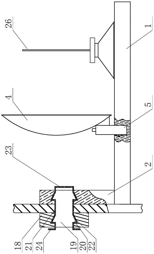
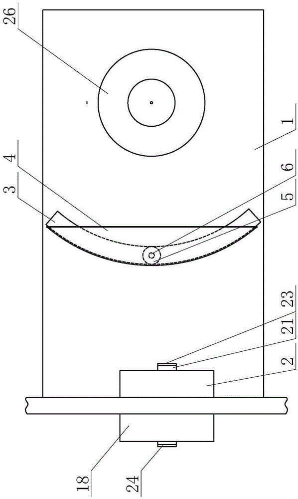
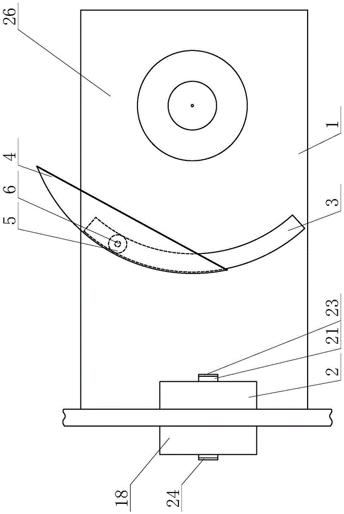
[0031] Such as Figure 1-7 As shown, this embodiment is an antenna fixing device for enhancing concentrator signals, including a horizontal plate 1 and a vertical plate 2, one end of the horizontal plate 1 is fixed to the lower part of the vertical plate 2, and a fixed structure is arranged on the vertical plate 2; An arc-shaped first chute 3 is set up, and an adjustment seat is arranged in the first chute 3, and a vertical curved signal receiver 4 is installed on the side of the adjustment seat; the adjustment seat includes an outer cylinder 5 and ...


PUM

PropertyMeasurementUnit
Vertical widthaaaaaaaaaa

Abstract

The invention discloses an antenna fixing apparatus for strengthening a concentrator signal. The antenna fixing apparatus comprises a transverse plate and a vertical plate, wherein a first sliding groove is formed in the transverse plate; an adjusting base is arranged in the first sliding groove; a signal receiver is mounted on the side face of the adjusting base; the adjusting base comprises an outer cylinder and an inner cylinder; the inner cylinder is arranged in the outer cylinder in a sleeving manner; a first spring is mounted between the inner bottom of the outer cylinder and the bottom surface of the inner cylinder; a strip-shaped opening is formed in the side wall of the outer cylinder; elastic clamping sheets are mounted in the strip-shaped opening; the lower ends of the elastic clamping sheets are hinged with the side wall of the outer cylinder; the upper ends of the elastic clamping sheets can be folded to the outer cylinder, and a fixing block is mounted at the upper ends of the elastic clamping sheets; a second sliding groove is formed in the fixing block; a supporting transverse rod is arranged in the second sliding groove; one end of the supporting transverse rod is movably in contact with the second sliding groove; the other end of the supporting transverse rod is horizontally fixed to the inner cylinder; an arc-shaped groove is formed in the side wall of the first sliding groove along the direction of the first sliding groove; and due to the matching of the arc-shaped groove and the elastic clamping sheets, the adjusting base can be fixed. The antenna fixing apparatus is steady in structure; and the signal receiving and transmission accuracy of the antenna is improved by additionally providing the signal receiver and the adjusting base.

Description

technical field [0001] The invention relates to an antenna fixing device, which belongs to auxiliary equipment for power operation, in particular to an antenna fixing device for realizing signal enhancement of a concentrator. Background technique [0002] At present, with the promotion of one meter per household and the transformation of urban and rural power grids, the use of smart cost-controlled meters has improved the management level of electricity consumption and the automatic meter reading function. Smart cost-controlled electricity meters are also called smart energy meters. They can standardize the entire network, reduce manufacturing and procurement costs, and can report operating status and other information through remote collection devices, automatically discover meter failures, and provide emergency repairs as soon as possible. The smart energy meter can also record the information of the electricity consumption process, and the power supply company will provid...

Claims


Application Information

Patent Timeline
IPC IPC(8): H01Q1/12
CPCH01Q1/1207
Inventor 王文超崔健米燕田慧王常营王雪莲谭淑丽王萍
Owner ZHANGQIU POWER SUPPLY CO OF STATE GRID SHANDONG ELECTRIC POWER CO
Learn More