Short distance optical magnification module, glasses, helmet and vr system
An optical magnification, short-distance technology, applied in the field of optical instruments, can solve the problem of low experience, and achieve the effect of large eye movement range, high-quality imaging effect, and good field of view.
- Summary
- Abstract
- Description
- Claims
- Application Information
AI Technical Summary
Problems solved by technology
Method used
Image

Examples
Embodiment 1
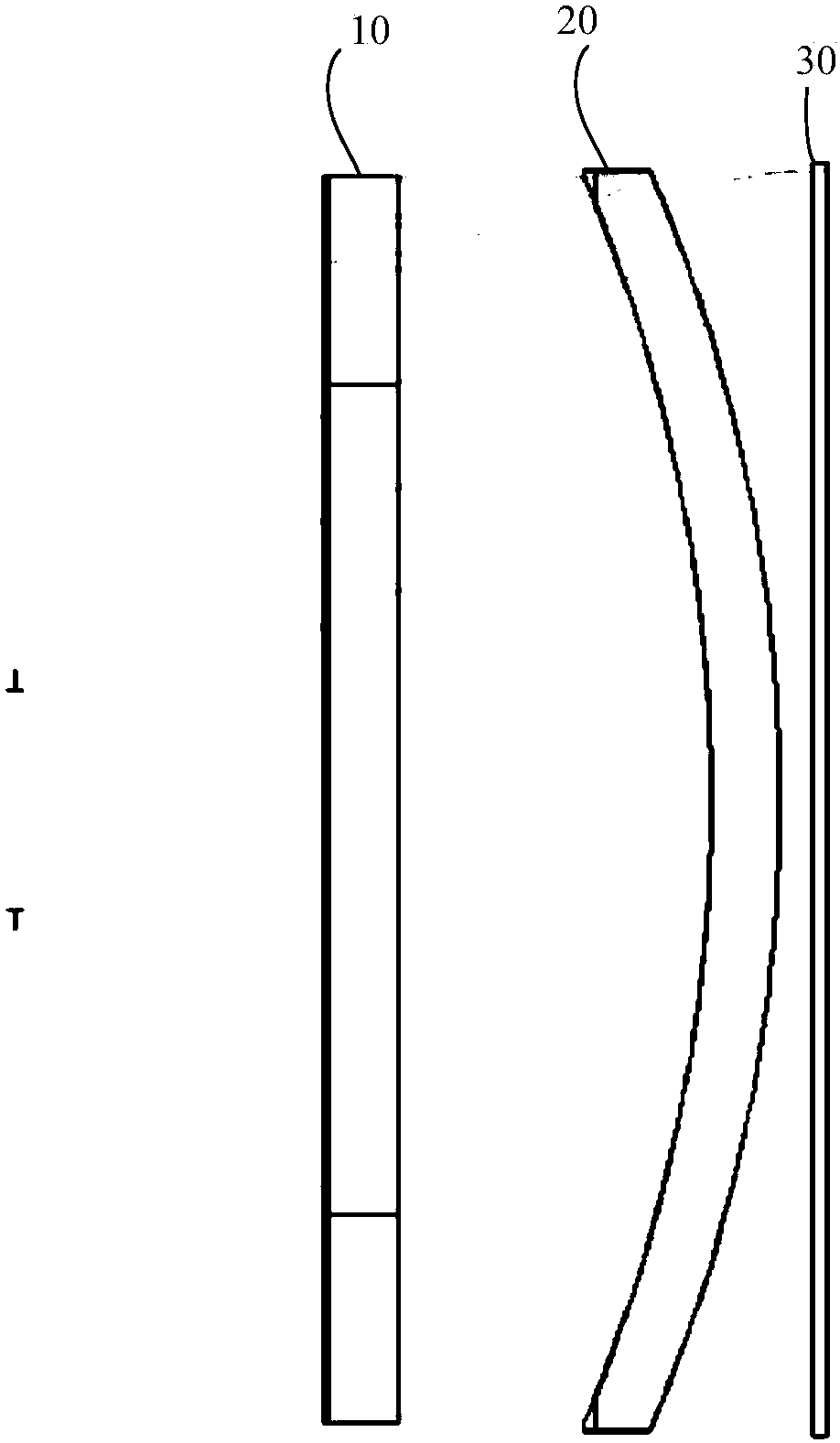
[0077] Such as figure 2 As shown, in the short-distance optical magnification module, the first focal length f2 of the second lens 20 is designed to be equal to the system focal length F, where,
[0078] The specific design parameters of the short-distance optical amplification module are shown in Table 1:
[0079]
[0080]
[0081] In Table 1, the first row OBJ represents the relevant design parameters of the object plane; the second row STO represents the diaphragm in the optical system, and the aperture is 7mm; the third row represents the reflective polarizer and the third row in the optical module A diaphragm formed by a phase retarder, the type of the diaphragm is STANDARD (standard surface), the material is PMMA, the diameter is 24.685mm, and the aspheric coefficient is 0; the fourth row and the fifth row represent the first lens, respectively The data corresponding to the first optical surface E1 and the second optical surface E2 of 10, the radius of curvature of the first...
Embodiment 2
[0089] Such as Image 6 As shown, in the short-distance optical magnification module, the focal length of the first lens 10 is designed to be 10.4F, and the first focal length f2 of the second lens 20 is equal to the system focal length of 1.5F, where,
[0090] The specific design parameters of the short-distance optical amplification module are shown in Table 3:
[0091] Surf
Type
Radius of curvature
thickness
Material
Mirror radius
Aspheric coefficient
OBJ
STANDARD
Infinity
-200
476.7014
0
STO
STANDARD
Infinity
9
9
0
2
STANDARD
Infinity
4
H-QK3L
30.04656
0
3
STANDARD
-134.133
5.996206
33.5536
0
4
STANDARD
Infinity
4
H-QK3L
47.00138
0
5
STANDARD
-99
-4
MIRROR
48.08787
0
6
EVENASPH
Infinity
-5.996206
48.07203
0
7
EVENASPH
-134.133
-4
H-QK3L
47.88681
0
8
STANDARD
Infinity
-0.2
PMMA
47.64044
0
9
STANDARD
Infinity
0
MIRROR
47.61382
0
10
STANDARD
Infinity
0.2
PMMA
47.61382
0
11
STANDARD
Infinity
4
H-QK3L
47.58719
0
12
EVENASPH
-134.133
5.996206
47.33418
0
13
EVENASPH
Infinity
4
H-QK3L...
Embodiment 3
[0100] Such as Picture 10 As shown, in the short-distance optical magnification module, the focal length of the first lens 10 is designed to be 6.7F, and the first focal length f2 of the second lens 20 is equal to the system focal length of 1.6F, where,
[0101] The specific design parameters of the short-distance optical amplification module are shown in Table 5:
[0102]
[0103]
[0104] In Table 5, the second row represents the paraxial design of PARAXIAL; the fourth row represents the relevant parameter design in the diaphragm formed by the reflective polarizer in the optical module and the first phase retarder; the sixth and seventh rows Represents the relevant parameter design of the first lens 10, wherein the second optical surface E2 of the first lens 10 is an EVENASPH aspheric surface; the eighth and ninth rows represent the relevant parameter design of the first lens 20, wherein The third optical surface E3 of the first lens 20 is an EVENASPH aspheric surface. For the ...
PUM
 Abstract
Description
Claims
Application Information
 - R&D
- Intellectual Property
- Life Sciences
- Materials
- Tech Scout
- Unparalleled Data Quality
- Higher Quality Content
- 60% Fewer Hallucinations
Browse by: Latest US Patents, China's latest patents, Technical Efficacy Thesaurus, Application Domain, Technology Topic, Popular Technical Reports.
© 2025 PatSnap. All rights reserved.Legal|Privacy policy|Modern Slavery Act Transparency Statement|Sitemap|About US| Contact US: help@patsnap.com