
Radar power supply automatic test method

A power supply automatic testing and automatic testing technology, applied in the direction of power supply testing, etc., can solve the problems of hidden safety hazards, a large number of manual operations, complicated and tedious means of testing and fault finding, etc., to achieve the effect of convenient maintenance and prevention of wrong insertion

Inactive Publication Date: 2016-06-15
ECU ELECTRONICS INDAL
View PDF7 Cites 16 Cited by
  • Summary
  • Abstract
  • Description
  • Claims
  • Application Information

AI Technical Summary

Problems solved by technology

[0002] Existing power supply testing and detection of faulty power supplies mainly use manual testing methods, the methods of testing and fault finding are complex and cumbersome, and have potential safety hazards
Existing power supply test systems require a lot of manual operations to conduct routine tests and records for power supplies, and cannot provide fault location and maintenance guidance for power supplies

Method used


Image

  • Radar power supply automatic test method
  • Radar power supply automatic test method

Examples


Embodiment Construction

[0032] The present invention will be further explained below in conjunction with the drawings:

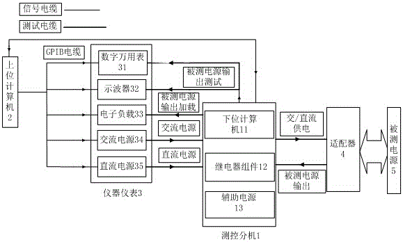
[0033] Such as figure 1 As shown, the radar power supply automatic test method, the adopted system is composed of a measurement and control extension, a host computer, instrumentation, and an adapter. The measurement and control extension includes a lower computer, relay components and auxiliary power supplies; the instrumentation includes a digital multimeter, oscilloscope, electronic load, and AC Power supply and DC power supply.

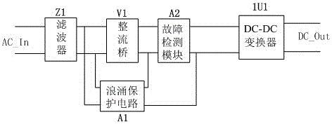
[0034] Such as figure 2 As shown, a radar switching power supply is taken as an example of the power supply under test. The power input is AC power and three DC outputs, each of which is mainly composed of filter Z1, rectifier bridge V1, surge protection circuit A1, fault detection module A2, and fuse F1 , DC_DC conversion module U1, inductor 1L1. Mainly test its input failure, input short-circuit failure, no-load output failure, full-load output failure...


PUM


Abstract

The invention relates to an automatic testing method for a radar power supply, comprising the following steps: a switching power supply under test is connected to a measurement and control extension through an adapter; at the same time, the test system supplies power to the power supply under test through the adapter, and at the same time collects various working states of the power supply under test including input voltage, output voltage, ripple. According to the rated input and output parameters of the power supply, the upper computer completes the routine test and fault location of the power supply through the automatic test system. If the test result is normal, the test interface of the upper computer will prompt that the normal result is normal; if there is a power failure, the test interface of the upper computer will prompt the fault test result, including the scope and form of the fault. While realizing the automatic test, the invention can detect whether there is a fault in the power supply, find out the location of the fault, and facilitate maintenance by technicians.

Description

Technical field [0001] The invention relates to the technical field of radar power supply testing, in particular to a radar power supply automatic testing method. Background technique [0002] Existing power supply testing and faulty power supply detection mainly adopt manual testing methods, and the testing and fault finding methods are complicated and cumbersome, and there are hidden safety hazards. The existing power supply test system requires a lot of manual operation to perform routine tests and records for the power supply, and cannot locate and repair the power supply. Summary of the invention [0003] The purpose of the present invention is to provide an automatic test method for radar power supply, which can complete the automatic test of the power supply and simultaneously check whether the power supply equipment has a fault, and locate the fault. [0004] In order to achieve the above objectives, the present invention adopts the following technical solutions: [0005] An...

Claims


Application Information

Patent Timeline
Patent Type & Authority Applications(China)
IPC IPC(8): G01R31/40
CPCG01R31/40
Inventor 夏田李雪唐泰楼高文何庆庆
Owner ECU ELECTRONICS INDAL
Learn More