
Measuring method for optical interval of refraction and reflection system with hollow main lens

A technology of optical interval and measurement method, which is applied in the direction of testing optical performance, measuring device, geometric characteristics/aberration measurement, etc. It can solve the problems that the optical interval between primary and secondary mirrors cannot be directly and accurately measured, and achieve the effect of improving the accuracy of assembly and adjustment

Active Publication Date: 2016-06-15
西安应用光学研究所
View PDF10 Cites 7 Cited by
  • Summary
  • Abstract
  • Description
  • Claims
  • Application Information

AI Technical Summary

Problems solved by technology

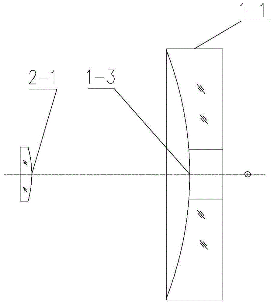
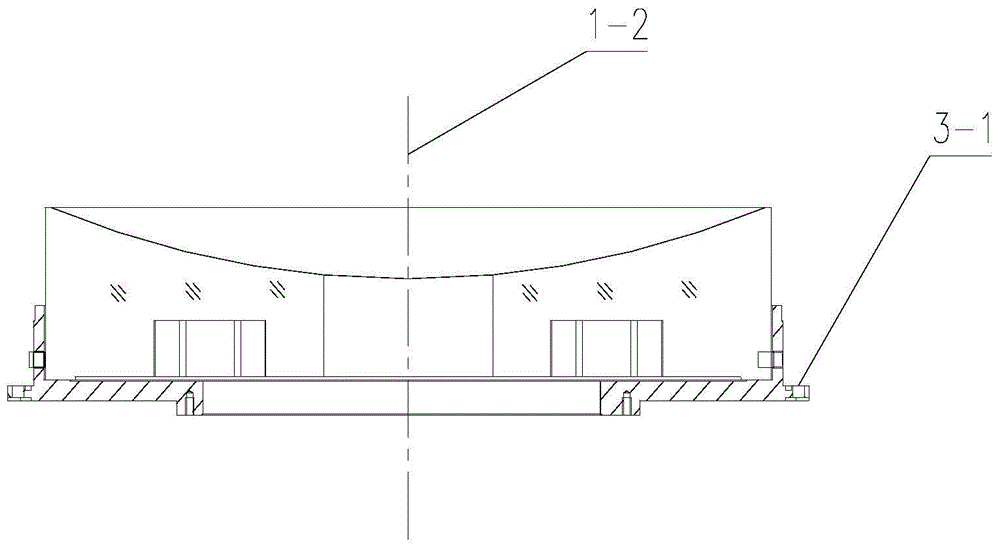
[0006] Aiming at the technical problem that the optical distance between the primary and secondary mirrors cannot be directly and accurately measured due to the hollow primary mirror in the optical-mechanical adjustment of the existing catadioptric optical system, the present invention proposes a method for measuring the optical distance of the catadioptric system containing the hollow primary mirror , use a three-coordinate measuring instrument to measure the outer circle of the primary mirror to determine the center position of the primary mirror, and then use a three-coordinate measuring instrument to collect points on the surface of the primary mirror once and determine the z-direction size between the point position and the apex position of the primary mirror, combined with the main The z-direction dimension of the mirror mount mounting surface, calculate the distance between the vertex of the primary mirror space and the mounting surface of the primary mirror mount, and then measure the distance from the mounting surface of the primary mirror mount on the main barrel to the vertex of the secondary mirror, thus calculating the primary and secondary Mirror Optical Spacing Dimensions

Method used


Image

  • Measuring method for optical interval of refraction and reflection system with hollow main lens
  • Measuring method for optical interval of refraction and reflection system with hollow main lens
  • Measuring method for optical interval of refraction and reflection system with hollow main lens

Examples


Embodiment Construction

[0031] Describe the present invention below in conjunction with specific embodiment:

[0032] The present invention mainly aims at the technical problem that the optical distance between the primary and secondary mirrors cannot be directly and accurately measured due to the hollow primary mirror in the optical-mechanical adjustment of the existing catadioptric optical system, and proposes a method for the optical distance of the catadioptric system containing the hollow primary mirror. The measurement method is to use a coordinate measuring instrument such as a three-coordinate measuring instrument to measure the outer circle of the primary mirror to determine the center position of the primary mirror, and then use a three-coordinate measuring instrument to collect points on the surface of the primary mirror once and determine the location of the point and the apex of the primary mirror. The z-direction dimension of the position, combined with the z-direction dimension of the m...


PUM


Abstract

The invention provides a measuring method for the optical interval of a refraction and reflection system with a hollow main lens. A glued seat of the main lens is measured by a coordinate measuring instrument, the spatial position of a central axis of the main lens is obtained by taking the external circle of the main lens as the reference, certain point is measured in the surface of the main lens, the size of the top point of the main lens is obtained, the size of the top point is compared with the size of an installation surface of the seat of the main lens to obtain the distance between the top point of the main lens and the installation surface of the seat of the main lens, and the optical interval between the main lens and an auxiliary lens is obtained quantitatively and accurately by combining the distance between the installation surface of the seat of the main lens and the top point of the auxiliary lens. Precise adjustment of the system is further guided, the measuring method is objective, the problem that the optical interval of the refraction and reflection system with the hollow main lens cannot be measured is solved, and compared with a present adjustment method, the adjustment precision is improved, and the measuring method is suitable for precise adjustment of the optical interval of different types of refraction and reflection systems with hollow main lenes.

Description

technical field [0001] The invention belongs to the technical field of optical machine assembly and adjustment, and mainly relates to a method for measuring the optical interval of a catadioptric system, in particular to a method for measuring the optical interval of a catadioptric system containing a hollow primary mirror. Background technique [0002] In order to increase the detection distance of the optical system, the aperture of the optical system is getting larger and larger. When the aperture of the optical system reaches a certain level, it is difficult for the refraction objective lens system to meet the requirements. However, the Cassegrain system has a compact structure and a larger aperture. , greatly improving the detection distance, and with the advancement of aspheric surface processing and detection technology, the optical system of the Cassegrain system can adopt a paraboloid-hyperboloid all-aspherical objective lens structure, which can reduce the length an...

Claims


Application Information

Patent Timeline
Patent Type & Authority Applications(China)
IPC IPC(8): G01B21/16G01M11/02
CPCG01B21/16G01M11/0242
Inventor 惠刚阳杨海成姜峰左晓舟刘欣张燕王章利王中强王智超
Owner 西安应用光学研究所
Learn More