A tool for testing bobbin coil binding power and a method therefor

A skeleton coil and testing tooling technology, applied in the direction of measuring devices, mechanical devices, instruments, etc., can solve the problems of skeleton coil insulation, insulation paint peeling, etc., and achieve the effect of ensuring product quality and good effect

Active Publication Date: 2016-06-08
FLIGHT AUTOMATIC CONTROL RES INST
View PDF9 Cites 12 Cited by
  • Summary
  • Abstract
  • Description
  • Claims
  • Application Information

AI Technical Summary

Problems solved by technology

This type of coil requires that the coils be firmly bonded to each other by heating, and it is sufficient that no loose wires occur in the working environment. For control, when several coils need to be removed to adjust the electrical performance, the insulating varnish on the inner layer of the enameled wire may be peeled off due to the excessive bonding force between the coils, resulting in insulation problems in the skeleton coil

Method used


Image

  • A tool for testing bobbin coil binding power and a method therefor

Examples


Embodiment Construction

[0013] The present invention will be described in detail below in conjunction with the accompanying drawings.

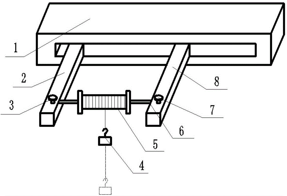
[0014] see figure 1 , a skeleton coil bonding force testing tool, consisting of a guide rail base 1, a first cantilever rod 2, a first locking screw 3, a load 4, a skeleton coil 5, a mandrel 6, a second locking screw 7 and a second cantilever The guide rail base 1 is a bottom plate with a guide rail groove; the first cantilever rod 2 and the second cantilever rod 8 are placed in the guide rail groove of the guide rail base 1 in parallel, and the distance between the first cantilever rod 2 and the One end of the second cantilever rod 8 is provided with a mounting hole where the mandrel 6 can be placed, and the first locking screw 3 and the second locking screw 7 for fixing the mandrel 6 are respectively provided on the mounting hole, and the mandrel 6 is One two ends are respectively matched with the mounting holes of the first cantilever rod 3 and the second cantile...


PUM


Abstract

The invention relates to a tool for testing bobbin coil binding power and a method therefor. The tool comprises a guide rail base (1), a first suspended rod (2), a first lock screw (3), a load (4), a bobbin coil (5), a central spindle (6), a second lock screw (7) and a second suspended rod (8). At the tangential direction of the outmost coil layer of the bobbin coil (5), the load (4) is hung on a self-adhesive varnished wire at an end of the bobbin coil (5), the weight of the load (4) is increased gradually until the self-adhesive varnished wire on which the load (4) is hung is separated from the bobbin coil (5), and then the weight of the load (4) is a binding power value of the outmost coil layer of the bobbin coil (5). Through results of coil binding power testing, heating temperature and heating time in heat bonding process parameters can be adjusted, and therefore binding power values of bobbin coils can be quantified and controlled.

Description

technical field [0001] The invention relates to a tool and method for testing the bonding force of a skeleton coil. Background technique [0002] At present, more and more fly-by-wire flight control systems are used in the aviation field to control the flight of aircraft. Electromagnetic sensors, motors, transformers, solenoid valves and other components containing various electromagnetic components are an important part of the system feedback. Generally, the coils inside these parts can be made of ordinary enameled wires. After processing, they will go through processes such as pre-baking, dipping, dripping, and drying. It takes several hours or even dozens of hours of work. Produces pungent, noxious gas. With the continuous development of my country's basic industry, a self-adhesive enameled wire coated with self-adhesive paint has attracted the attention of the aviation manufacturing industry and has been gradually introduced. At present, the self-adhesive enameled wire...

Claims


Application Information

Patent Timeline
Patent Type & Authority Applications(China)
IPC IPC(8): G01N19/04
Inventor 樊正云姚远林莉
Owner FLIGHT AUTOMATIC CONTROL RES INST
Why Eureka
Try Eureka