
Structure of vehicle direction light

A vehicle direction and structure technology, applied to road vehicles, motor vehicles, lighting device components, etc., can solve problems such as concave deformation, affecting the aesthetics of the lampshade 12, and different cooling rates

Active Publication Date: 2016-06-08
KYMCO
View PDF6 Cites 0 Cited by
  • Summary
  • Abstract
  • Description
  • Claims
  • Application Information

AI Technical Summary

Problems solved by technology

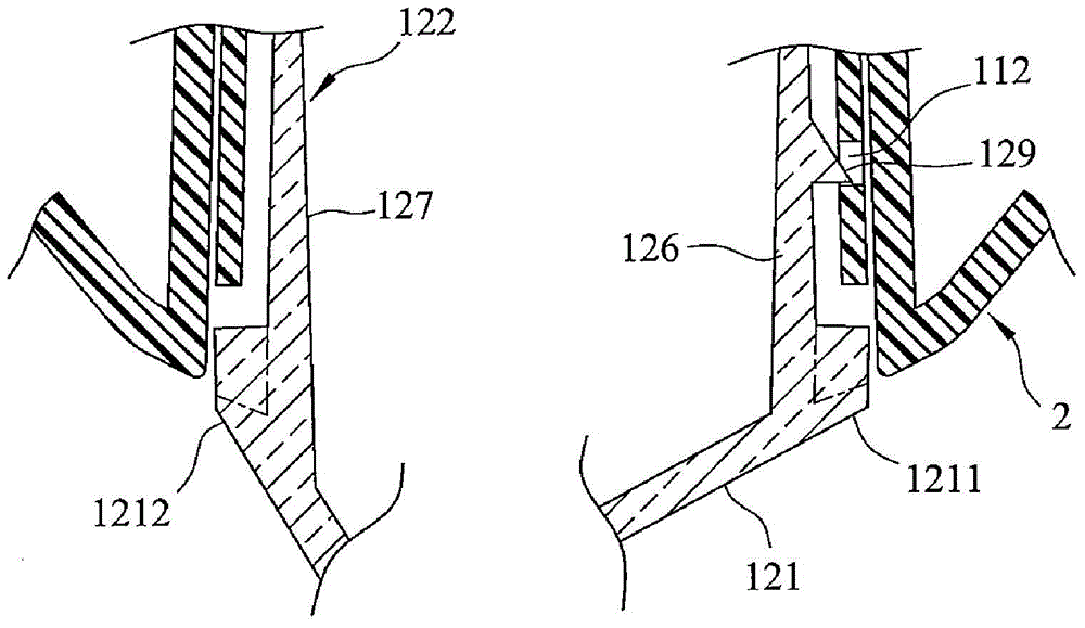
However, because the thickness of the meat supplemented by the two side edges 1211 and 1212 of the light guide wall 121 as shown by the imaginary line in the figure is different, the cooling rate after demolding is different, and the light guide wall 121 of the lampshade 12 is thicker. The thicker side edge 1212 is prone to shrinkage and deformation, which affects the aesthetics of the lampshade 12

Method used


Image

  • Structure of vehicle direction light
  • Structure of vehicle direction light
  • Structure of vehicle direction light

Examples


Embodiment Construction

[0019] refer to Figure 4 , 5 , 6, is an embodiment of the structure (structure) of the vehicle direction light of the present invention, including a lamp holder 3 , a lampshade unit 4 , and a light emitting unit 5 .

[0020] The lamp holder 3 has a first inner extension section 31 and two first outer extension sections 32, the first inner extension section 31 and the first outer extension section 32 are connected around each other and jointly define a circle for use. A carrying space 33 for accommodating the light emitting unit 5 . In addition, the lamp holder 3 also has a peripheral wall 34 , an inner peripheral wall 35 protruding from the carrying space 33 and spaced from the peripheral wall 34 , and an end connecting the peripheral wall 34 and the inner peripheral wall 35 . The connecting wall 36 , the peripheral wall 34 , the inner peripheral wall 35 and the connecting wall 36 jointly define an accommodating groove 37 . The portion of the peripheral wall 34 correspondi...


PUM


Abstract

The invention provides a structure of a vehicle direction light. The structure of the vehicle direction light comprises a light base, a light cover unit and a light emitting unit arranged in the light cover unit. A plurality of first clamping parts and a plurality of second clamping parts are arranged on the outer side of the light base in a protruding mode. The outer side of the light cover unit is provided with a plurality of first connecting parts used for being connected with the first clamping parts and a plurality of second connecting parts used for being connected with the second clamping parts, the light cover unit and the light base can be combined to be a whole easily and rapidly without the aid of a locking element, and whole assembling operation is quite convenient; in addition, due to the fact that no locking element needs to be used, the appearance integrity and the aesthetic property of the direction light can be made good.

Description

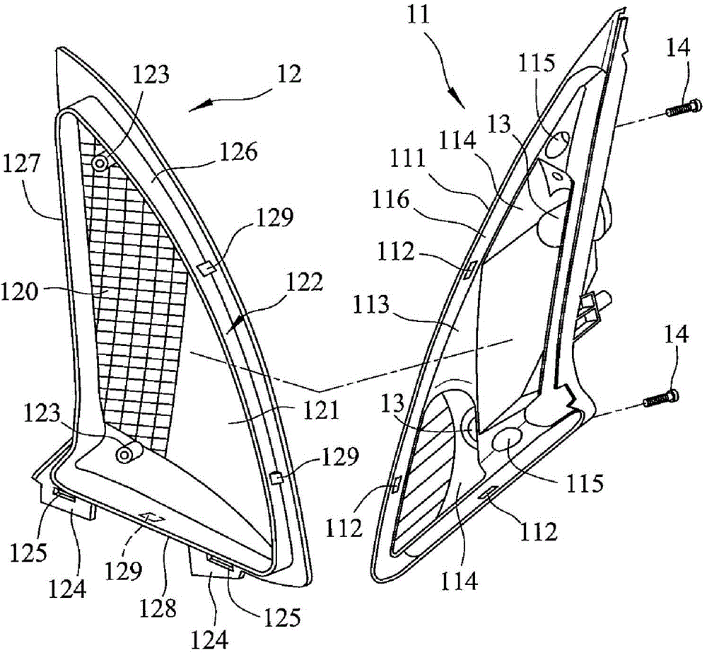
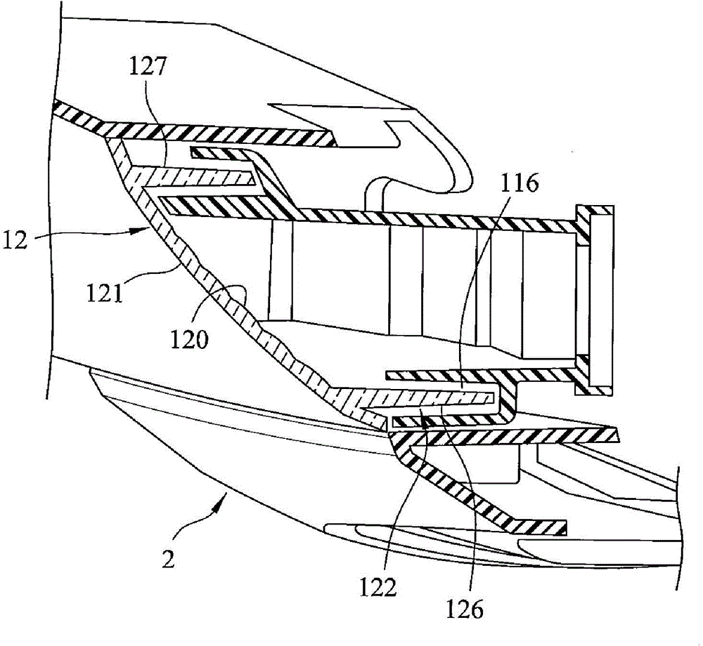
technical field [0001] The invention relates to a lamp, in particular to a structure of a vehicle direction lamp. Background technique [0002] refer to figure 1 , 2 , is an existing vehicle direction light, mainly comprising a lamp holder 11, a light-transmitting lampshade 12 combined with the lamp holder 11, two lampshades arranged on the lamp holder 11 and capable of illuminating toward the lampshade 12 Light illuminator 13, and two screws 14. Wherein, the lamp holder 11 has a surrounding wall 111, a plurality of clamping holes 112 provided on the surrounding wall 111, a protruding block 113 located in the surrounding area of ​​the surrounding wall 111, two spaced apart formed on the protruding block 113 includes a groove 114 through which the lighting lamp 13 passes, two perforations 115 disposed on the protruding block 113 , and a slot 116 between the surrounding wall 111 and the protruding block 113 . The lampshade 12 has a light guide wall 121 and a connecting wal...

Claims


Application Information

Patent Timeline
Patent Type & Authority Applications(China)
IPC IPC(8): F21S8/10F21V17/10F21W101/02F21W101/12F21W107/10
Inventor 林建成
Owner KYMCO
Learn More