
Trace oil injection device

An oil injection device and micro-quantity technology, which is applied in the direction of quantitative devices, distribution devices, lubricating oil control valves, etc., can solve the problems of high-frequency oil injection, low utilization rate of lubricating oil, limited application range, etc., and avoid waste of lubricating oil , improve service life and save lubricating oil

Inactive Publication Date: 2016-06-08
山东朗鑫机械设备有限公司
View PDF9 Cites 0 Cited by
  • Summary
  • Abstract
  • Description
  • Claims
  • Application Information

AI Technical Summary

Problems solved by technology

The problems of this intermittent oil injection machine are: 1. The amount of lubricating oil pumped by the lubricating oil pump at a time is relatively large, the utilization rate of lubricating oil is low, and high-frequency oil injection cannot be realized, and the scope of application is limited; 2. Only through the lubricating oil pump The lubricating oil is extracted intermittently, and the oil nozzle cannot cooperate with the lubricating oil pump; 3. After the lubricating machine is started, it will continue to work, and when lubricating some moving parts, there will be problems of insufficient lubrication; 4. The existing oil filling The grease nipple of the machine will leak lubricating oil after being used for a long time

Method used


Image

  • Trace oil injection device
  • Trace oil injection device
  • Trace oil injection device

Examples


Embodiment 1

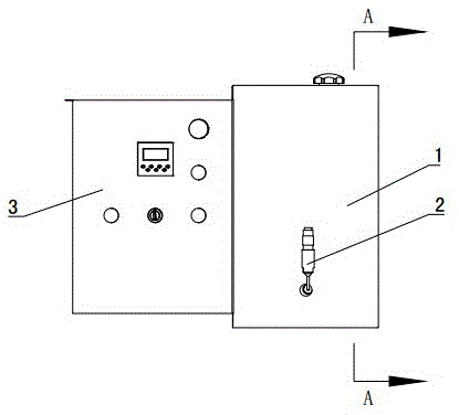
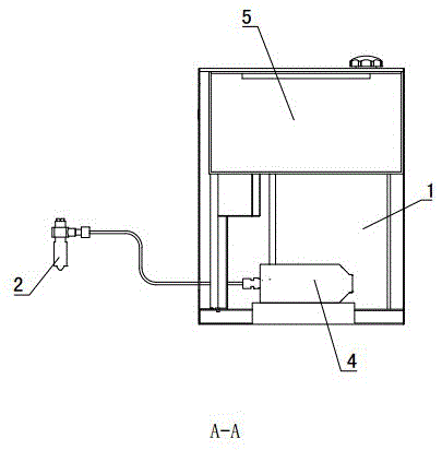
[0036] Such as Figure 1~2 As shown: the oil tank 5, the oil pump 4 and the control device are installed in the box body 1, and the oil outlet nozzle 2 is arranged outside the box body 1. The box body 1 is a cuboid, and the box body 1 is provided with a box body door 3, and a control button and a display screen are installed on the box body door 3, which are used to control the micro-greasing device and display the working state of the micro-greasing device.

[0037] Fuel tank 5 is installed on the top of casing 1, and the filling port of fuel tank 5 is arranged on the top, and stretches out the top surface of casing 1, and fuel tank 5 is plexiglass material, and is provided with strainer at the oil inlet, ensures that fuel tank 5 The lubricating oil inside is clean and pollution-free.

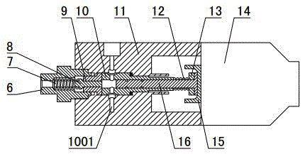
[0038] The oil pump 4 is installed in the lower middle part of the casing 1, and the oil inlet of the oil pump 4 is communicated with the oil outlet at the bottom of the oil tank 5 through a ...

Embodiment 2

[0059] Such as Figure 5As shown: the difference between embodiment 2 and embodiment 1 is: the right end of the plunger 16 is provided with a plunger oil hole 1601, the plunger oil hole 1601 is "L" shaped, and the end of the vertical part of the plunger oil hole 1601 It is arranged on the side of the plunger 16 , the end of the horizontal part of the plunger oil hole 1601 is arranged on the end surface of the right end of the plunger 16 , and the pump oil chamber is located on the right side of the plunger 16 . When the plunger 16 moves rightward to the left dead center of the stroke, the volume of the pump oil chamber is the largest. At this time, the plunger oil hole 1601 communicates with the plunger sleeve oil hole 1001, and the lubricating oil enters the pump oil chamber along the plunger oil hole 1601. , and when the plunger 16 moves to the right, the lubricating oil in the pump oil chamber is pumped out. The plunger oil hole 1601 can limit the lubricating oil entering ...


PUM


Abstract

The invention provides a trace oil injection device and belongs to the technical field of oil injection equipment. The trace oil injection device comprises an oil tank (5), an oil pump (4), an oil outlet nozzle (2) and a control device, wherein an oil inlet hole of the oil pump (4) is communicated with the bottom of the oil tank (5), an oil outlet hole of the oil pump (4) is communicated with an oil inlet hole of the oil outlet nozzle (2), and a plunger (16) of the oil pump (4) is connected with an electromagnet (14) pushing the plunger to move axially. The device is further provided with a detection unit used for detecting to-be-lubricated equipment, and the electromagnet (14) and the detection unit are both connected with the control device. The trace oil injection device is provided with the detection unit, the detection unit can detect equipment where oil is to be injected and uploads signals to the control device, the control device controls the oil pump to be started and stopped, the electromagnet pushes the plunger to move, the oil injection frequency is controlled by the electromagnet, high-frequency oil injection can be realized, besides, the oil injection frequency is convenient to adjust, and accordingly, intermittent oil injection can be realized according to motions of the equipment where oil is to be injected.

Description

technical field [0001] A micro-volume oil injection device belongs to the technical field of oil injection equipment. Background technique [0002] The lubricating machine is a device that provides a small amount of lubricating oil during mechanical action. The lubricating machine mainly includes an oil tank for holding lubricating oil, a lubricating oil pump for extracting lubricating oil, and a lubricating oil pump for spraying lubricating oil to the mechanism to be lubricated on the nozzle. When the oil injection machine lubricates the equipment, it usually supplies oil continuously, that is, during the operation of the equipment, the oil injection machine continuously supplies oil to the equipment. This type of oil injection machine wastes more lubricating oil, and the usage rate of lubricating oil is very high. Low. [0003] Intermittent oiling machine is a kind of equipment that intermittently provides lubricating oil for mechanical equipment. Most of the existing in...

Claims


Application Information

Patent Timeline
IPC IPC(8): F16N7/38F16N27/02F16N23/00F16N25/00
CPCF16N7/38F16N23/00F16N25/00F16N27/02
Inventor 李国铭孙永涛王海军孙永春王振王铁君
Owner 山东朗鑫机械设备有限公司
Learn More