A junction box capable of storing wires
A junction box and electric wire technology, applied in the field of junction boxes, can solve the problems of insufficient utilization of the use effect and lack of junction boxes
- Summary
- Abstract
- Description
- Claims
- Application Information
AI Technical Summary
Problems solved by technology
Method used
Image

Examples
Embodiment 1
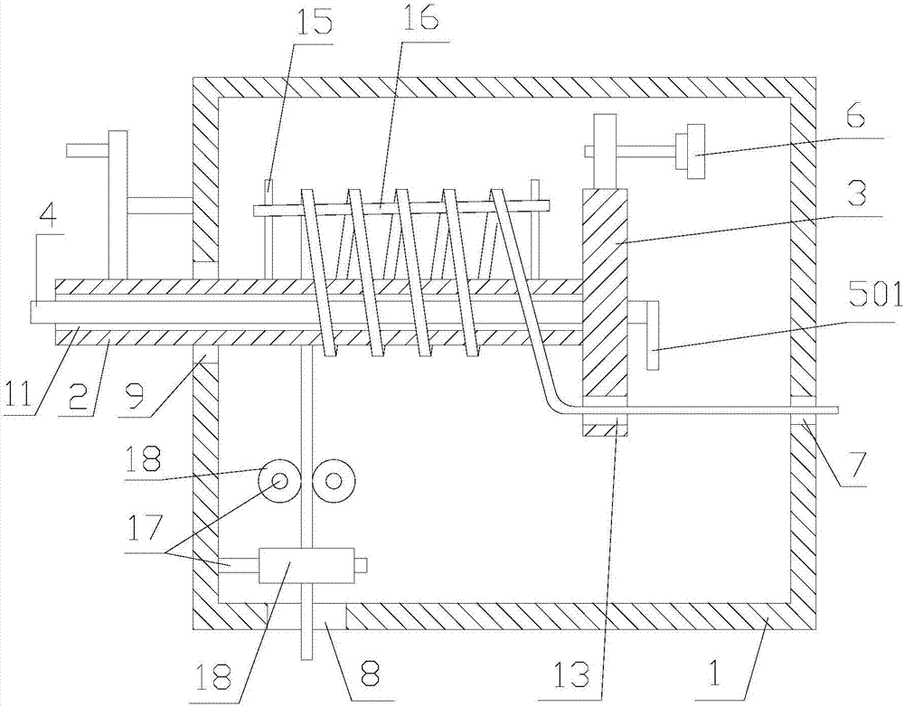
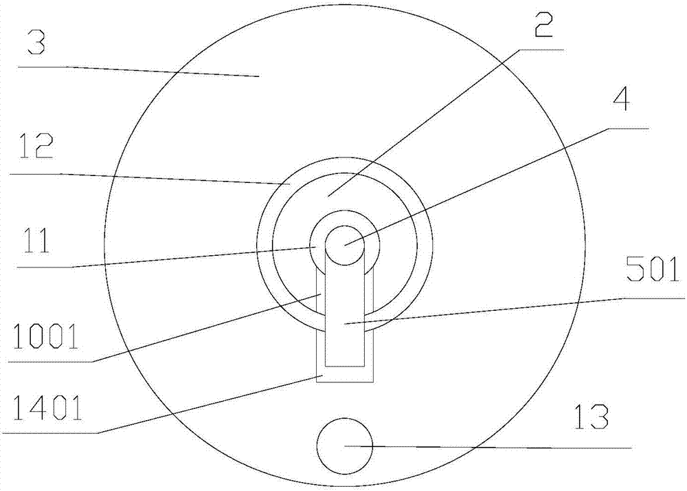
[0031] Reference figure 1 , 2 :
[0032] A junction box capable of storing wires provided by the present invention includes a box body 1, a rotating shaft 2, a rotating wheel 3, a connecting rod 4, a connecting plate 501, a driving mechanism 6, and a plurality of limit units.
[0033] The box body 1 is provided with an inlet hole 7, an outlet hole 8, and a through hole 9. The inlet hole 7 and the through hole 9 are respectively placed on two opposite side walls of the box body 1, and the axis of the inlet hole 7 is connected to the through hole. The axis of the hole 9 is parallel.
[0034] The rotating shaft 2 is placed in the through hole 9, and the rotating shaft 2 is rotatably connected with the through hole 9. The first end of the rotating shaft 2 is placed inside the box body 1 and close to the wire inlet 7, and the first end surface of the rotating shaft 2 is provided with a receiving groove 1001 The second end of the rotating shaft 2 is placed outside the box body 1; the axis...
Embodiment 2
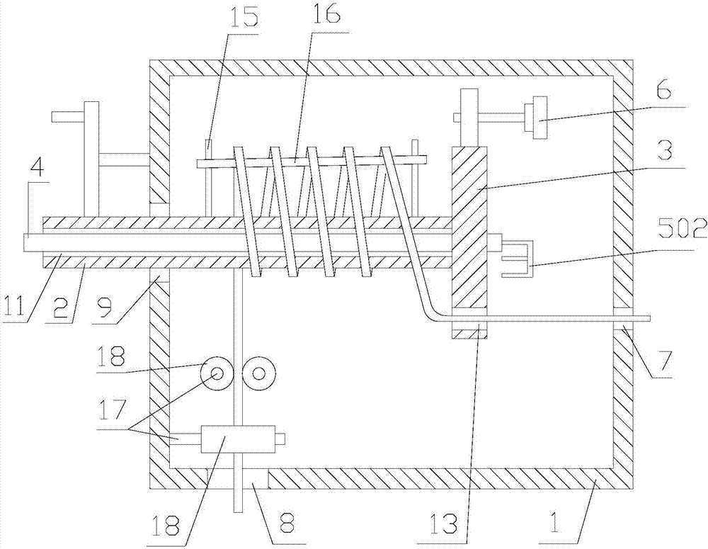
[0049] Combine image 3 , 4 :
[0050] A junction box capable of storing wires provided by the present invention includes a box body 1, a rotating shaft 2, a rotating wheel 3, a connecting rod 4, a connecting plate 502, a driving mechanism 6, and a plurality of limit units.
[0051] The box body 1 is provided with an inlet hole 7, an outlet hole 8, and a through hole 9. The inlet hole 7 and the through hole 9 are respectively placed on two opposite side walls of the box body 1, and the axis of the inlet hole 7 is connected to the through hole. The axis of the hole 9 is parallel.
[0052] The rotating shaft 2 is placed in the through hole 9, and the rotating shaft 2 is rotatably connected with the through hole 9. The first end of the rotating shaft 2 is placed inside the box body 1 and close to the wire inlet 7, and the first end surface of the rotating shaft 2 is provided with a receiving groove 1002 The second end of the rotating shaft 2 is placed outside the box body 1; the axis o...
PUM
 Abstract
Description
Claims
Application Information
 - R&D
- Intellectual Property
- Life Sciences
- Materials
- Tech Scout
- Unparalleled Data Quality
- Higher Quality Content
- 60% Fewer Hallucinations
Browse by: Latest US Patents, China's latest patents, Technical Efficacy Thesaurus, Application Domain, Technology Topic, Popular Technical Reports.
© 2025 PatSnap. All rights reserved.Legal|Privacy policy|Modern Slavery Act Transparency Statement|Sitemap|About US| Contact US: help@patsnap.com