
Horizontal type multistage centrifugal pump

A centrifugal pump and horizontal technology, applied in the field of horizontal multistage centrifugal pumps, can solve the problems of inconvenient maintenance and maintenance, consumption of manpower, financial resources, easy wear and tear of balancing devices, etc., to achieve simplicity and compactness, improve transmission power and efficiency, Smooth running effect

Active Publication Date: 2016-06-01
GUANGDONG LINGXIAO PUMP IND
View PDF8 Cites 1 Cited by
  • Summary
  • Abstract
  • Description
  • Claims
  • Application Information

AI Technical Summary

Problems solved by technology

[0002] There are many kinds of centrifugal pumps in the prior art, the main structure of which is connected to a secondary motor at one end of the main shaft, and is provided with a water inlet and outlet housing, and an impeller is installed in the cavity. Due to the high speed of the motor, it can generally reach 3000 rpm / min, or even higher, resulting in a fragile pump body and a short service life
[0003] In addition, due to the unbalanced axial force of the existing multi-stage centrifugal pumps, the structure of the balance plate or the balance drum is generally used to realize the axial balance of the multi-stage centrifugal pump, but the balance device is easy to wear, and the repair and maintenance are inconvenient, not only It consumes a lot of manpower and financial resources, which may seriously cause abnormal production and even equipment failure

Method used


Image

  • Horizontal type multistage centrifugal pump
  • Horizontal type multistage centrifugal pump

Examples


Embodiment 1

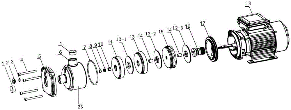
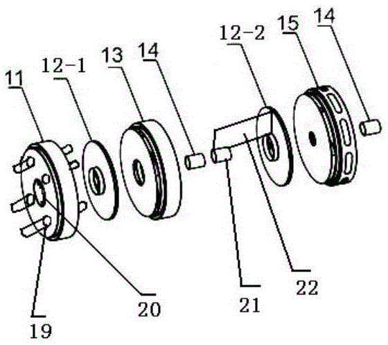
[0024] A horizontal multi-stage centrifugal pump, including a pump casing assembly 23, a primary guide vane assembly 11, a three-stage impeller, a middle body assembly 13, a water outlet assembly 15, and a motor 18; the three-stage impeller includes a primary impeller 12-1, Secondary impeller 12-2, last stage impeller 12-3, the middle segment assembly 13 is arranged between the primary impeller 12-1 and the secondary impeller 12-2, and the water outlet section assembly 15 is arranged in the secondary Between the stage impeller 12-2 and the last stage impeller 12-3, the primary guide vane assembly 11 is arranged on the side of the primary impeller 12-1 away from the middle body assembly 13, the primary guide vane assembly 11 and the The primary impeller 12-1 is connected with interference fit, the primary guide vane assembly 11 has a plurality of guide vane outlets 19 radially extending along the primary guide vane assembly 11, one end of the guide vane outlet 19 faces the prima...

Embodiment 2

[0026]A horizontal multi-stage centrifugal pump, including a pump casing assembly 23, a primary guide vane assembly 11, a three-stage impeller, a middle body assembly 13, a water outlet assembly 15, and a motor 18; the three-stage impeller includes a primary impeller 12-1, Secondary impeller 12-2, last stage impeller 12-3, the middle segment assembly 13 is arranged between the primary impeller 12-1 and the secondary impeller 12-2, and the water outlet section assembly 15 is arranged in the secondary Between the stage impeller 12-2 and the last stage impeller 12-3, the primary guide vane assembly 11 is arranged on the side of the primary impeller 12-1 away from the middle body assembly 13, the primary guide vane assembly 11 and the The primary impeller 12-1 is connected with interference fit, the primary guide vane assembly 11 has a plurality of guide vane outlets 19 radially extending along the primary guide vane assembly 11, one end of the guide vane outlet 19 faces the primar...


PUM


Abstract

The invention provides a horizontal type multistage centrifugal pump. The horizontal type multistage centrifugal pump comprises a pump shell assembly (23), a primary-stage guide blade assembly (11), a third-stage impeller, a middle segment body assembly (13), a water outlet segment assembly (15) and a motor (18); the third-stage impeller comprises a primary-stage impeller (12-1), a second-stage impeller (12-2) and a tail-stage impeller (12-3); the middle segment body assembly (13) is arranged between the primary-stage impeller (12-1) and the second-stage impeller (12-2); the primary-stage guide blade assembly (11) is arranged on one side, far away from the middle segment body assembly (13), of the primary-stage impeller (12-1); the primary-stage guide blade assembly (11) is provided with a plurality of guide blade outlets (19) extending in the radial direction of the primary-stage guide blade assembly (11); one end of each guide blade outlet (19) faces the impeller concave face of the primary-stage impeller (12-1), and the other ends of the guide blade outlets (19) are communicated with an inner cavity of the pump shell assembly (23); and a water pumping outlet (6) is formed in the wall of the inner cavity of the pump shell assembly (23).

Description

technical field [0001] The invention relates to the technical field of pump bodies, in particular to a horizontal multistage centrifugal pump. Background technique [0002] There are many kinds of centrifugal pumps in the prior art, the main structure of which is connected to a secondary motor at one end of the main shaft, and is provided with a water inlet and outlet housing, and an impeller is installed in the cavity. Due to the high speed of the motor, it can generally reach 3000 rpm / min, or even higher, resulting in a fragile pump body and a short service life. [0003] In addition, due to the unbalanced axial force of the existing multi-stage centrifugal pumps, the structure of the balance plate or the balance drum is generally used to realize the axial balance of the multi-stage centrifugal pump, but the balance device is easy to wear, and the repair and maintenance are inconvenient, not only It consumes a lot of manpower and financial resources, which may seriously ...

Claims


Application Information

Patent Timeline
Patent Type & Authority Applications(China)
IPC IPC(8): F04D1/06F04D13/06F04D29/22F04D29/62F04D29/08F04D29/66
CPCF04D1/06F04D13/06F04D29/086F04D29/185F04D29/22F04D29/225F04D29/628F04D29/669
Inventor 梁瑞军陈家潮黄厚清
Owner GUANGDONG LINGXIAO PUMP IND
Learn More