
Reactive gas delivery device and chemical vapor deposition or epitaxial layer growth reactor

A technology of chemical vapor deposition and conveying device, which is applied in gaseous chemical plating, coating, metal material coating process, etc., can solve the different process effects of different substrates, cannot guarantee the same shape and size of the gas conveying device, air leakage, etc. question

Active Publication Date: 2018-04-24
ADVANCED MICRO FAB EQUIP INC CHINA
View PDF5 Cites 0 Cited by
  • Summary
  • Abstract
  • Description
  • Claims
  • Application Information

AI Technical Summary

Problems solved by technology

[0004] In the prior art, most gas conveying devices are designed to use gas conveying pipes to realize the conveying of different reaction gases, welding and processing many components together not only increases the difficulty of processing, but also because of the distance between the gas conveying pipes and different gases The sealing effect between the plates is not good, which increases the risk of gas leakage; in other designs, a gas delivery device is provided, which is welded by welding a plurality of hollow elongated tubular gas distribution elements side by side and at intervals At the same time, components such as gas diffusers and cooling pipes are welded under the long tubular gas distribution components, but these welding components are very easy to cause water leakage and air leakage, and it is impossible to ensure that the components of each air inlet are exactly the same during welding , therefore, the shape and size of each gas delivery device cannot be guaranteed to be consistent. In addition, after a process, the gas delivery device is easily deformed, resulting in different process effects for different substrates in the same reaction chamber.
If the processing parameters of each gas delivery device cannot be guaranteed to be exactly the same, when placed in the reactor, the processing technology of different reactors will be different, which will seriously affect the uniformity of substrate processing in different reactors, resulting in a Processing results vary between batches of substrates (chamber-to-chamber)
In addition, in these designs, there is also the problem of non-uniform gas delivery to the treatment area due to differences in gas diffusion rates between the tubular gas distribution elements

Method used


Image

  • Reactive gas delivery device and chemical vapor deposition or epitaxial layer growth reactor
  • Reactive gas delivery device and chemical vapor deposition or epitaxial layer growth reactor
  • Reactive gas delivery device and chemical vapor deposition or epitaxial layer growth reactor

Examples


Embodiment Construction

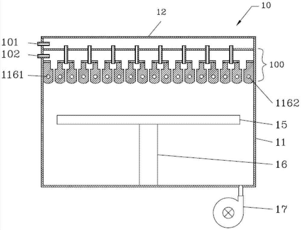
[0047] figure 1 A front view cross-sectional schematic view of a reactor provided according to an embodiment of the present invention is shown. The reactor may be used for chemical vapor deposition or epitaxial layer growth, but it should be understood that it is not limited to such applications.

[0048] The reactor 10 includes an outer wall 11 and a top wall 12 surrounding the reaction chamber. At least one substrate carrier 15 and a support device 16 for supporting the substrate carrier 15 are arranged in the reactor 10. In the deposition or epitaxial layer growth reactor, the support device 16 can drive the substrate carrier 15 to rotate, so as to realize the smooth progress of the deposition process or the epitaxial layer growth process. Above the substrate carrier 15 and below the top wall 12, a reaction gas delivery device 100 is arranged, and the reaction gas delivery device 100 is used to deliver at least two groups of different reaction gases to the processing area ...


PUM


Abstract

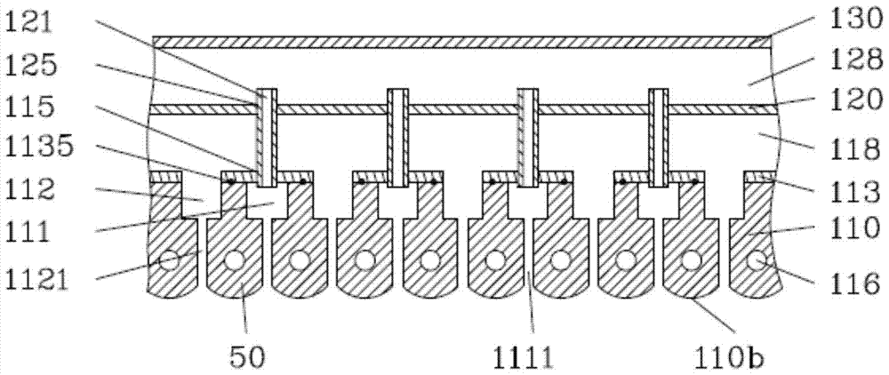
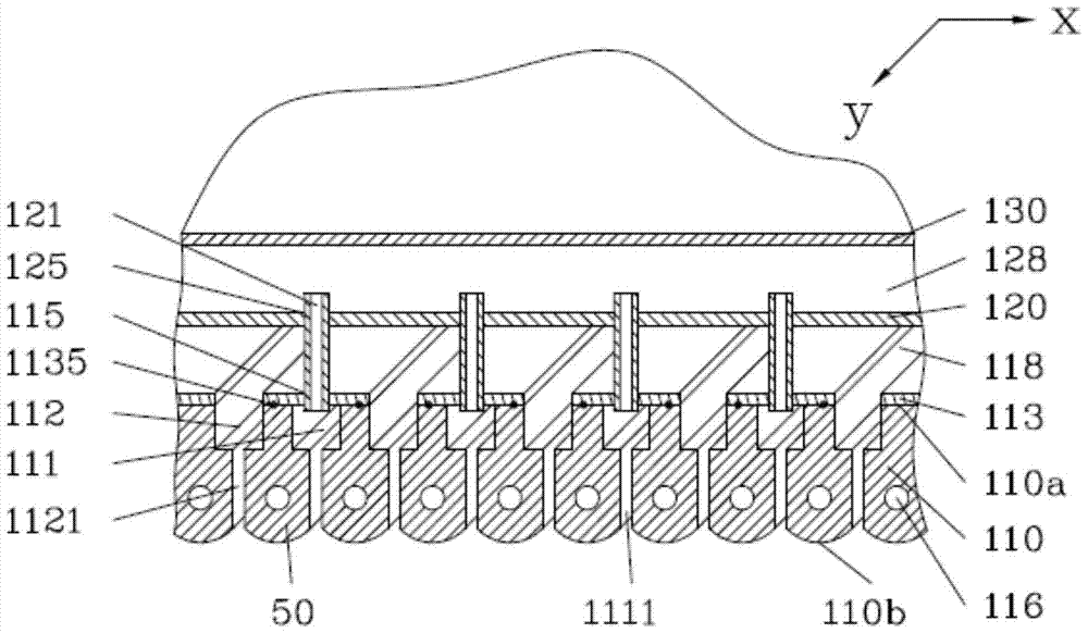
The invention discloses a gas delivery device for a chemical vapor deposition or epitaxial layer growth reactor, which comprises a separation plate and a gas delivery plate, a first gas diffusion area is formed above the separation plate, the separation plate and the gas delivery plate A second gas diffusion area is formed between the gas delivery plates; the upper surface of the gas delivery plate is alternately provided with mutually parallel elongated first gas diffusion grooves and vertically elongated second gas diffusion grooves, and the first gas diffusion grooves A first gas outlet channel and a second gas outlet channel are respectively arranged at the bottom of the second gas diffusion groove, which are respectively used to transport the gas in the first gas diffusion area and the gas in the second gas diffusion area to the processing area; The lower surface of the gas conveying plate between the outlet of the adjacent first gas outlet channel and the outlet of the second gas outlet channel is arc-shaped or tapered.

Description

technical field [0001] The present invention relates to the manufacture of semiconductor devices, in particular to a device for growing epitaxial layers or performing chemical vapor deposition on substrates such as substrates. Background technique [0002] During the production process of growing epitaxial layers or performing chemical vapor deposition on substrates such as substrates, the design of the reactor is critical. Reactors in the prior art come in a variety of designs, including: horizontal reactors, in which the substrates are mounted at an angle to the incoming reactant gases; planetary rotating horizontal reactors, In this reactor, the reaction gas is passed through the substrate horizontally; and in the vertical reactor, when the reaction gas is injected downward on the substrate, the substrate is placed on the substrate carrier in the reaction chamber and Relatively high speed rotation. This high-speed rotating vertical reactor is one of the most commerciall...

Claims


Application Information

Patent Timeline
Patent Type & Authority Patents(China)
IPC IPC(8): C23C16/455
Inventor 姜银鑫杜志游
Owner ADVANCED MICRO FAB EQUIP INC CHINA
Learn More