Buoy release device

A technology for releasing devices and buoys, which is applied in the direction of buoys, transportation and packaging, special-purpose ships, etc. It can solve the problems of complicated assembly and disassembly, difficult recovery, and inapplicability, and achieve the effects of reliable operation, avoiding messy cables, and simple structure

Active Publication Date: 2017-09-19
中国船舶重工集团公司第七〇二研究所
View PDF5 Cites 0 Cited by
  • Summary
  • Abstract
  • Description
  • Claims
  • Application Information

AI Technical Summary

Problems solved by technology

The above buoy release method has the following defects: First, the shape design of the buoy is limited by the layout of the fan-shaped plate, and cannot be designed according to the shape of the underwater equipment, which affects the hydrodynamic performance of the underwater equipment to a certain extent; The method is not suitable for underwater equipment such as large-depth submersibles; third, there are many components, complex assembly and disassembly, and it is not easy to restore once it is used, so it is not suitable for various tests and adjustments of underwater equipment

Method used


Image

  • Buoy release device
  • Buoy release device
  • Buoy release device

Examples


Embodiment Construction

[0022] The specific embodiments of the present invention will be described below in conjunction with the drawings.

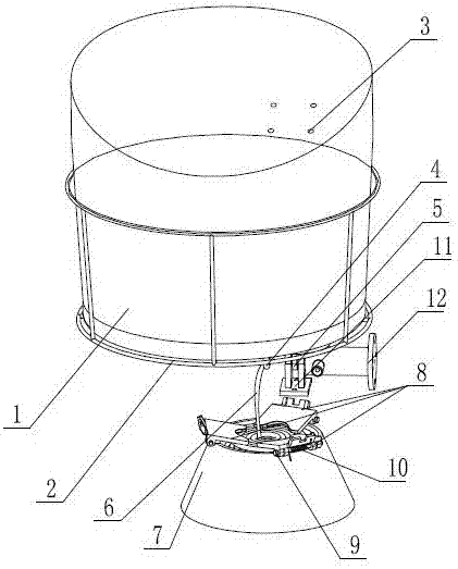
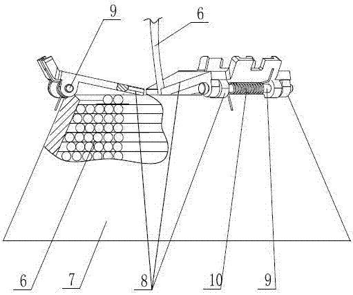
[0023] see figure 1 , figure 2 , image 3 , The present invention includes buoy 1, buoy 1 is movably placed in protection frame 2, embedded part 3 is loaded into buoy 1 from the bottom of buoy 1, and hook one 4 and hook two 5 are fixedly connected to the bottom of embedded part 3. The hook 4 is fixed to one end of the rope 6, and the other end of the rope 6 is fixed at the bottom of the rope frame 7. The body of the rope 6 is layered in the rope frame 7; the top of the rope frame 7 is evenly distributed with at least two pressure plates in the circumferential direction 8. The outer side of the pressure plate 8 is hinged with the cable frame 7 through a circumferential pin 9; the inner end of the pressure plate 8 is closed on the top opening of the cable frame 7, and the inner ends of the pressure plates 8 are formed at least to accommodate The accommodating space...


PUM


Abstract

The invention discloses a buoy releasing device. The buoy releasing device comprises a buoy which is movably arranged in a protective frame, wherein an embedded part is arranged in the buoy; the bottom of the embedded part extends out of the buoy and is fixedly connected to two hangers; one hanger is fixedly connected to a mooring rope; the other end of the mooring rope is fixed to the bottom of a mooring rope frame; a mooring rope body is coiled in the mooring rope frame layer by layer; the top of the mooring rope frame is uniformly provided with at least two pressure plates in a peripheral direction; the outer sides of the pressure plates are hinged with the mooring rope frame through a peripheral pin roll; the inner side cover heads of the pressure plates cover the top opening of the mooring rope frame; and single mooring rope at least can be accommodated between the inner side end heads of the pressure plates; a torsion spring is arranged on the pin roll; the hook heads at the two ends of the torsion spring respectively abut against the outer side end surfaces of the pressure plates and the outer wall surface of the mooring rope frame; oil cylinder piston rods are arranged in the other hanger and lug holes of a connecting base in a penetration mode; the inner cavity of an oil cylinder body is divided into two; an oil inlet is formed in a cavity where the piston rods are located; an axial spring is arranged in another cavity; and the oil cylinder body, the mooring rope frame, the connecting base and the protective frame are fixedly arranged on underwater equipment. By virtue of the buoy releasing device, the buoy is simple and reliable to lock and release.

Description

Technical field [0001] The invention relates to a water rescue device, in particular to a release device of a water rescue buoy. Background technique [0002] Emergency buoys are key equipment in underwater equipment such as submersibles. They are used to identify the location of the submersible when there is an abnormal situation in the underwater equipment, so that rescuers can search and rescue. In response to the functional requirements of the emergency buoy, the structure of the device is sturdy, simple, reliable and can be manipulated by any person. The driving mode of the life-saving buoy does not depend on the electric power source that may be damaged inside the underwater equipment. [0003] Emergency buoys are usually locked to underwater equipment. When rescue is needed, the buoys need to be released to the surface. In the prior art, the release of emergency buoys generally adopts the method of rotating sector plates, that is, equally divided along the circumference of t...

Claims


Application Information

Patent Timeline
Patent Type & Authority Patents(China)
IPC IPC(8): B63B22/08
CPCB63B22/08
Inventor 王璇高波古浪
Owner 中国船舶重工集团公司第七〇二研究所
Why Eureka
Try Eureka