
Spot adhesive feeding cold runner injection mold with twin stripper plates

An injection mold and stripper plate technology, applied in the field of double stripper plate cold runner dispensing injection molds, can solve problems such as affecting product aesthetics, material head pressing, unclean falling off, etc., to solve the problem of waste falling off and The effect of unclean shedding, convenient and rapid shedding, and reasonable structure design

Active Publication Date: 2016-06-01
SHANGHAI VEI SHENG AUTO PARTS MFG CO LTD
View PDF3 Cites 1 Cited by
  • Summary
  • Abstract
  • Description
  • Claims
  • Application Information

AI Technical Summary

Problems solved by technology

[0004] However, the existing point-in-glue cold runner injection mold adopts the traditional point-in-glue method. After the injection molding is opened, the waste head cannot fall off by itself, and the waste head must be removed manually or by a robot, which is prone to fall off and is not clean. When the upper and lower molds of the mold are closed, the material head is pressed, and the production cannot be performed after the mold is pressed, and the mold needs to be removed from the machine, which brings great difficulties to normal production.
At the same time, it will cause the injection point to be in the center of the outer surface of the product, leaving more or less injection marks on the appearance of the product, which directly affects the aesthetics of the product
[0005] Therefore, the applicant is committed to providing a double stripper plate cold runner point injection mold, which has a reasonable structural design, can solve the problem of waste falling off and falling off, and can make the produced product smooth in appearance, without further progress. Glue traces

Method used


Image

  • Spot adhesive feeding cold runner injection mold with twin stripper plates
  • Spot adhesive feeding cold runner injection mold with twin stripper plates
  • Spot adhesive feeding cold runner injection mold with twin stripper plates

Examples


Embodiment Construction

[0067] In order to more clearly illustrate the embodiments of the present invention or the technical solutions in the prior art, the specific implementation manners of the present invention will be described below with reference to the accompanying drawings. Obviously, the accompanying drawings in the following description are only some embodiments of the present invention, and those skilled in the art can obtain other accompanying drawings based on these drawings and obtain other implementations.

[0068] In order to make the drawing concise, each drawing only schematically shows the parts related to the present invention, and they do not represent the actual structure of the product. In addition, to make the drawings concise and easy to understand, in some drawings, only one of the components having the same structure or function is schematically shown, or only one of them is marked. In this article, "one" not only means "only this one", but also can mean "more than one". I...


PUM


Abstract

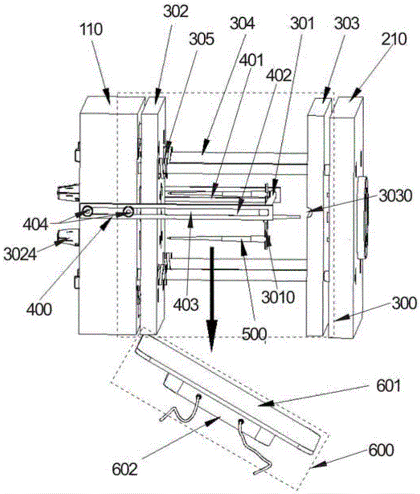
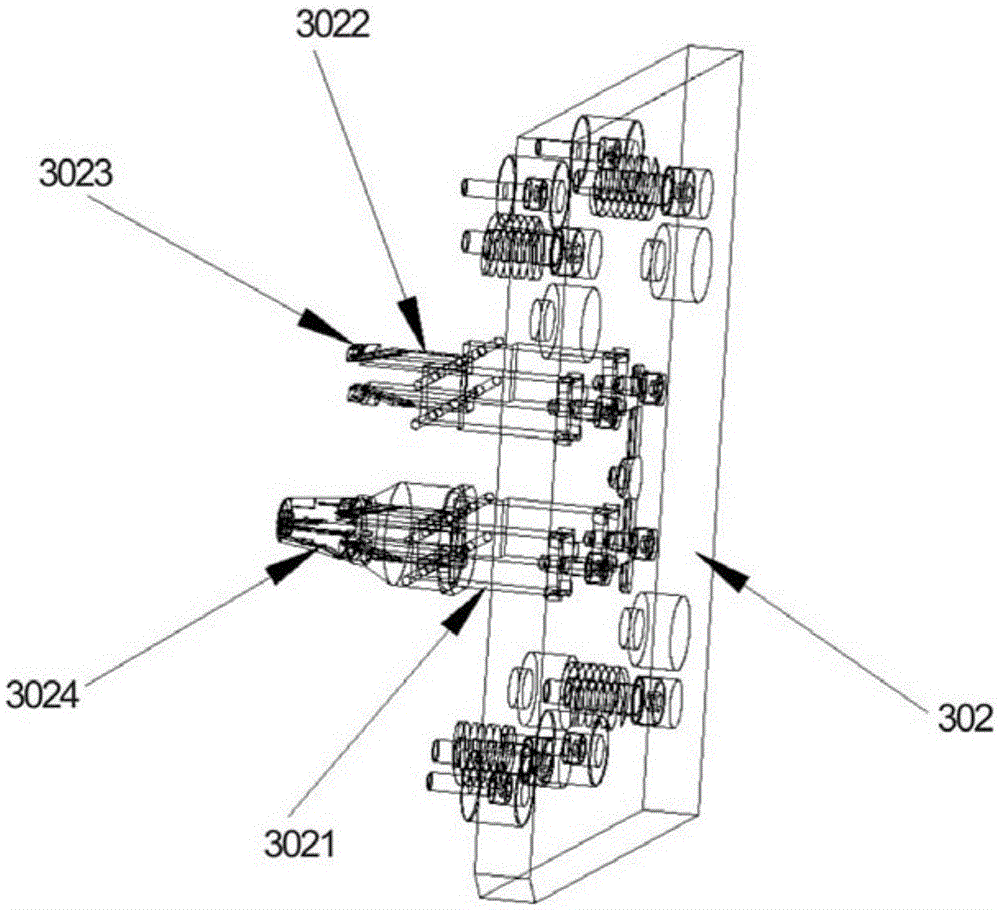
The invention provides a spot adhesive feeding cold runner injection mold with twin stripper plates. The spot adhesive feeding cold runner injection mold comprises an upper mold body, a lower mold body, an upper fixing plate for fixing the upper mold body and a lower fixing plate for fixing the lower mold body. A stripper device for being separated from a waste end is arranged between the upper mold body and the upper fixing plate. The stripper device is movably connected with the upper mold body through a connecting piece. The upper mold body and the upper fixing plate can be switched between the separated state and the combined state. When the upper mold body and the upper fixing plate are combined, the stripper device is clamped between the upper mold body and the upper fixing plate and connected with the waste end on one side of the upper mold body; when the upper mold body and the upper fixing plate are separated, the upper mold body moves towards one side of the lower mold body relative to the stripper device and drives the stripper device to draw the waste end on one side of the upper mold body out of the upper mold body through the connecting piece while moving. The spot adhesive feeding cold runner injection mold is reasonable in structural design; the problem that waste does not disengage thoroughly can be solved; the appearance of produced products can be made smooth, and no marks of adhesive feeding spots exist.

Description

technical field [0001] The invention relates to the technical field of injection mold mechanisms, in particular to a double stripper plate cold runner point-feed injection mold. Background technique [0002] As people's requirements for the appearance of various daily and industrial products are increasing, as the requirements for the appearance of various plastic products are increasing, their appearance conditions naturally become an important factor for people to evaluate the appearance of products. Among them, the gate position of the product, gate traces, welding Lines have become one of the elements that affect people's acceptance of products. [0003] The mold is an indispensable and important tool in injection molding. Injection molding is to inject hot-melt plastic material into the closed cavity with the required shape in the mold at high speed. After the plastic material is cooled and solidified, the mold is opened to push the solidified plastic product into the m...

Claims


Application Information

Patent Timeline
IPC IPC(8): B29C45/26B29C45/38
CPCB29C45/0025B29C45/2602B29C45/38B29C2045/0027
Inventor 尤山泉齐照山李德奇余沉林东峰
Owner SHANGHAI VEI SHENG AUTO PARTS MFG CO LTD
Learn More